Theremoelectric heat exchanger

a heat exchanger and thermoelectric technology, applied in the field of thermoelectric heat exchangers, can solve the problems of difficult to fit under or inside the car seat, the volume of the system is often too large to be mounted within, below or around the seat and the space available within the space of the temperature control system is severely limited

Inactive Publication Date: 2006-03-09
GENTHERM INC
View PDF26 Cites 37 Cited by
  • Summary
  • Abstract
  • Description
  • Claims
  • Application Information

AI Technical Summary

Benefits of technology

[0011] At least one of the first and second heat exchangers may be formed in segments to provide thermal isolation in the direction of flow. The heat transfer members may also be formed in segments to provide thermal isolat

Problems solved by technology

The amount of space available within, below and around the seat for such temperature control systems is severely limited.
Present temperature control systems are often too large to be mounted within, below or around vehicle seats.
Such systems are bulky and difficult to fit underneath or inside car seats.
Using thermoelectric devices to heat and cool the heat exchanger helps reduce the size of unit, but still requires a large volume for the combined heating and cooling system.
The ducting used with these systems is also bulky and difficult to use

Method used


Image

  • Theremoelectric heat exchanger
  • Theremoelectric heat exchanger
  • Theremoelectric heat exchanger

Examples


Embodiment Construction

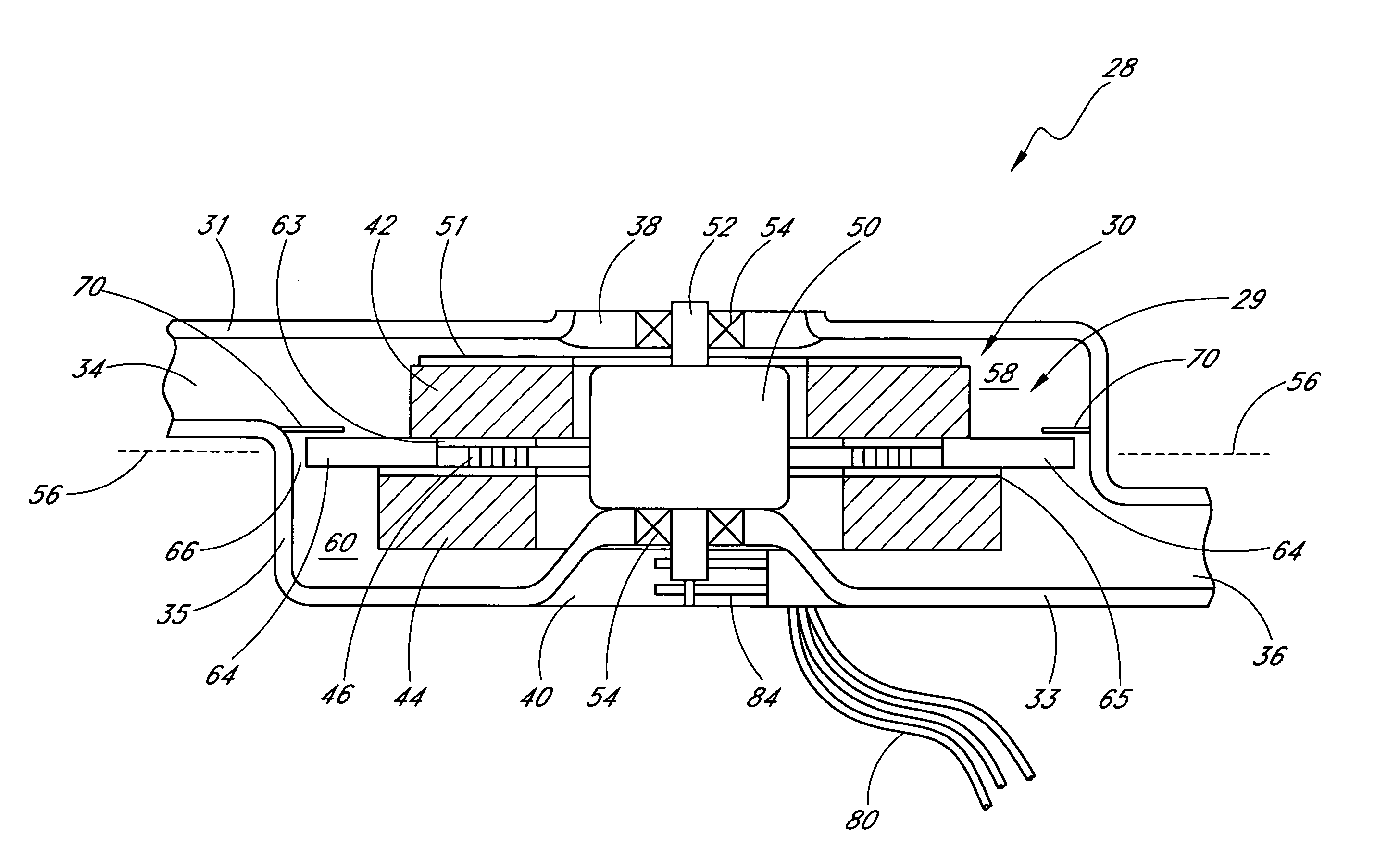
[0045] A variety of examples described below illustrate various configurations that may be employed to achieve desired improvements. The particular embodiments and examples are only illustrative and not intended in any way to restrict the general inventions presented and the various aspects and features of these inventions. In addition, it should be understood that the terms cooling side, heating side, cold side, hot side, cooler side and hotter side and the like do not indicate any particular temperature, but are relative terms. For examples, the “hot,”“heating” or “hotter” side of a thermoelectric element or array may be at ambient temperature, with the “cold,”“cooling” or “cooler” side at a cooler temperature than ambient. Conversely, the “cold,”“cooling” or “cooler” side may be at ambient with the “hot,”“heating” or “hotter” side at a higher temperature than ambient. Thus, the terms are relative to each other to indicate that one side of the thermoelectric is at a higher or lowe...


PUM


Abstract

Disclosed is a system for thermally conditioning and pumping a fluid. The system includes a thermoelectric heat exchanger having a thermoelectric device configured to pump heat. Heat exchangers are provided for transferring heat to and from the thermoelectric device and for generating a fluid flow across the thermoelectric device. The conditioned fluid may be placed in thermal communication with a variety of objects, such as a vehicle seat, or anywhere localized heating and cooling are desired. Thermal isolation may also be provided in the direction of flow to enhance efficiency.

Description

PRIOR APPLICATION DATA [0001] This application is a continuation of U.S. patent application Ser. No. 10 / 608,807 filed Jun. 27, 2003, which is a continuation-in-part of U.S. patent application Ser. No. 09 / 847,856 filed May 1, 2001 which is a continuation of U.S. application Ser. No. 09 / 428,018, filed Oct. 27, 1999 which is a continuation of U.S. application Ser. No. 09 / 076,518, filed May 12, 1998.BACKGROUND OF THE INVENTION [0002] The present invention relates to temperature control devices. More particularly, the present invention relates to a thermoelectric heat exchanger that is particularly useful for converting electricity to a flow of conditioned air. The air may be heated or cooled. [0003] Modern automobile seats may be equipped with temperature control systems that allow the occupant to vary the temperature of the seat by flowing temperature-controlled air through the seat covering. One type of system comprises a seat having a heat transfer system mounted therein, such as a t...

Claims


Application Information

Patent Timeline
IPC IPC(8): F25B21/02B60N2/90B60H1/00B60H1/22B60N2/56F04D29/58F25B21/04
CPCB60H1/00471B60H1/00478B60H1/2225B60N2/5635B60N2/5678H01L35/30B60N2/5692F04D29/5826F25B21/04F25B2321/0251B60N2/5657B60N2/5685F04D17/162F04D25/166F04D29/4246Y02B30/00H10N10/13F28D11/02
Inventor BELL, LON E.
Owner GENTHERM INC
Why Eureka
Try Eureka