Damping nut for screw-driven mechanism

Inactive Publication Date: 2006-03-09
BALL SCREW & ACTUATORS
View PDF8 Cites 17 Cited by
  • Summary
  • Abstract
  • Description
  • Claims
  • Application Information

AI Technical Summary

Benefits of technology

[0008] One object of the invention is to provide a simpler and more compact means for damping vibrations within a screw-driven mechanism. Another object of the invention is to provide a means for damping vibrations within a screw-driven mechanism that is effective over a wide range of frequencies an

Problems solved by technology

The disadvantage of lead screw assemblies is that they can develop unwanted noise and vibrations.
Lead screw assemblies may experience longitudinal, torsional, and transverse oscillations during operation.
Misalignments in the assembly and friction between the mating surfaces of the screw and nut threads typically may cause unwanted vibrations.
One of the drawbacks to this a

Method used


Image

  • Damping nut for screw-driven mechanism
  • Damping nut for screw-driven mechanism
  • Damping nut for screw-driven mechanism

Examples


Example

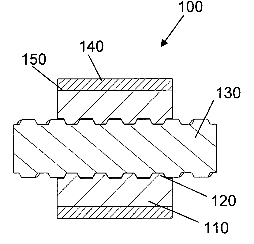
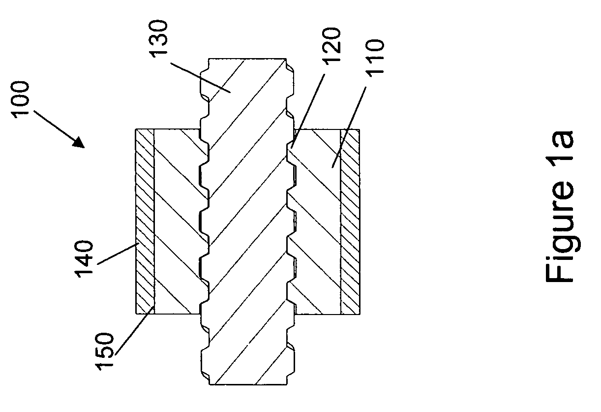
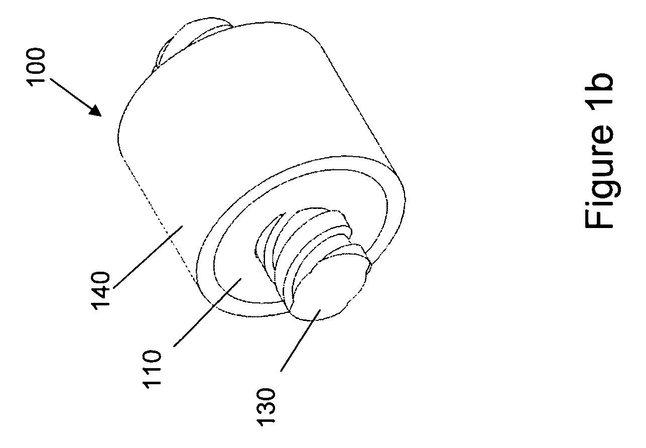
[0027]FIGS. 1a and 1b illustrate a first embodiment the vibration-damping nut, which comprises a nut body 110 with internal threads 120 engaged with the threads of a lead screw 130. A damping element, which may be a passive-damping element 140, is in contact with the nut body 110 at its outer surface 150. In a preferred embodiment, the damping element is a viscoelastic material (VEM) that transfers vibration-energy into thermal heat. In such embodiment, strain energy is transferred to the VEM through the surface 150 of the nut body 110. An adhesive can be used to attach the damping element 140 to the nut body surface 150, and a recess may alternatively or additionally be formed in the nut body 110 to hold the damping element.

[0028] In this and in other embodiments, the damping element is linked to a surface of the nut, which linking can be accomplished in a variety of manners, including friction fitting, by an adhesive, or other means. Contact between the damping element and the nu...

Example

[0032]FIG. 2 illustrates a second embodiment of a nut having a ring-shaped damping element 270 positioned such that it is in contact with the nut 260 at a radial surface 280, which is radial relative to a central axis of the nut body. This axis, of course, is essentially collinear with a central axis of the lead screw 130. In this specific embodiment, the radial surface 280 is at the end of the nut body 260, but need not be, but depends on the specific embodiment.

Example

[0033]FIGS. 3a and 3b illustrate a third embodiment of the present invention. In this, as well as in other selected embodiments, a mass 311 is in contact with a damping element 310. In this embodiment, the mass 311 is substantially tubular with a substantially circular cross section, though other cross-sections are very much possible in this and in other embodiments.

[0034] The mass 311 acts as a constraining layer to assist in creating strain in the damping element 310. This is accomplished because the mass 311 helps distribute loads evenly to the damping element 310, due to its rigidity. The mass 311 also acts as a tuning mass to assist in damping vibration. The magnitude of the mass (weight) of mass 311 is pre-selected for a desired behavior under anticipated loading conditions of the nut 300. By pre-selecting the mass (weight) of the mass 311, the natural frequencies (rotational and linear) can be adjusted, as can the natural frequencies of the entire system attached thereto. As...


PUM


Abstract

A vibration damper for screw-driven mechanical systems includes a nut body and one or more attached damping elements. The nut body includes internal threads for cooperating with a lead screw of a screw-driven mechanical system. The damping element may be a viscoelastic material or other material. The damping element may be arranged on an outer surface of the nut body, and may either be exposed or protected by another element. A tuning mass may be applied to the vibration damper by attachment to the damping element. In some embodiments, the damping element is arranged on a cantilever element of the nut body. In other embodiments, the damping element is segmented and is distributed such that air passages are formed between the damping element segments.

Description

BACKGROUND OF THE INVENTION [0001] 1. Field of the Invention [0002] The present invention relates to the field of screw-driven machinery, more particularly to traveling nuts in such screw-driven machinery. [0003] 2. Description of Related Art [0004] Precision lead screw and nut assemblies are used in positioning and locating applications, such as milling machines, automated metrology systems, factory automation systems, and wafer manufacturing equipment. Lead screw assemblies can also be used purely for the conversion of power or motion, such as jack lifts and elevator doors. Translating screws and nuts make very cost-effective solutions to motion applications. The disadvantage of lead screw assemblies is that they can develop unwanted noise and vibrations. Lead screw assemblies may experience longitudinal, torsional, and transverse oscillations during operation. There are many possible causes for these oscillations. Misalignments in the assembly and friction between the mating surf...

Claims


Application Information

Patent Timeline
IPC IPC(8): F16H25/20
CPCF16F15/1442Y10T74/18576F16H57/0006F16H25/20
Inventor UNG, TOM THANG
Owner BALL SCREW & ACTUATORS
Why Eureka
Try Eureka