Multistep transmission of a layshaft type

a multi-step transmission and layshaft technology, applied in the direction of shafts, bearings, mechanical equipment, etc., can solve the problem of short service li

Inactive Publication Date: 2006-03-09
ZF FRIEDRICHSHAFEN AG
View PDF5 Cites 18 Cited by
  • Summary
  • Abstract
  • Description
  • Claims
  • Application Information

AI Technical Summary

Benefits of technology

[0012] In addition, the bearing concept of the multi-speed transmission, according to the invention, offers advantages with regard to the configuration of the gearbox housing, since the third bearing mechanism and a fixed bearing of a gearbox input shaft, configured as a main gearbox input shaft, can be positioned in a mutual bearing plane and can be installed advantageously in a bearing plate from the point of view of costs and installation space.

Problems solved by technology

It is disadvantageous here, however, that the high gearing forces that are actively connected with the gear wheel pairs in the area of the countershaft that is configured as a hollow shaft (and which will be called the hollow countershaft below), which are caused by the different gear ratios of the gear wheel pairs between the gearbox input shafts and the countershaft, must be transferred via the bearing between the hollow countershaft and the main countershaft or main countershaft gear if there is a differential speed and, in addition, the forces that are conducted toward the main hollow countershaft must be introduced into the housing via the bearing mechanisms of the main countershaft within the housing if there is a renewed speed difference.
This arrangement is characterized by unfavorable load characteristic values that have, as a consequence, a short service life of the gearbox, which is undesirable from the point of view of the operating costs of a motor vehicle over its entire service life.

Method used


Image

  • Multistep transmission of a layshaft type
  • Multistep transmission of a layshaft type
  • Multistep transmission of a layshaft type

Examples


Embodiment Construction

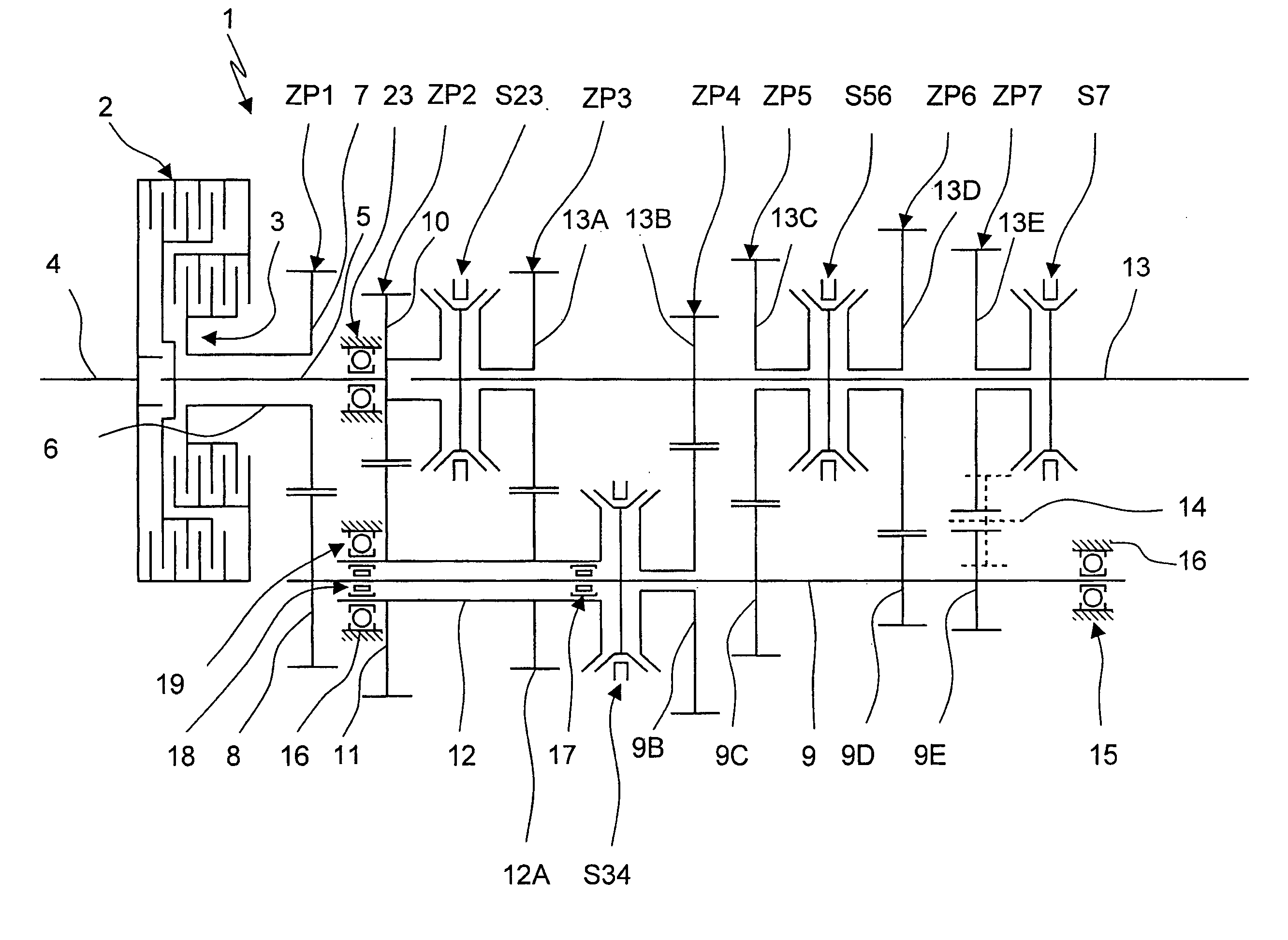
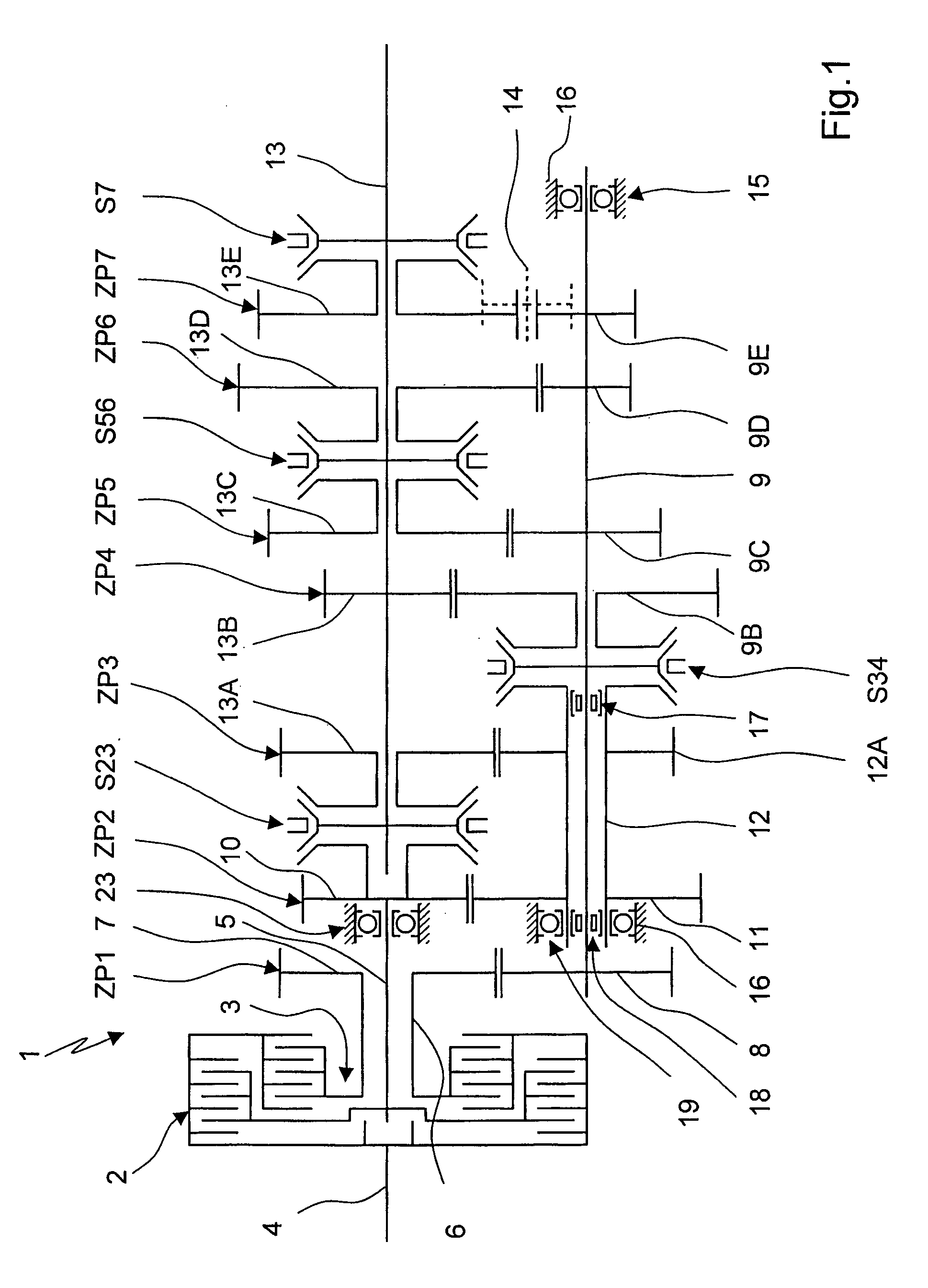
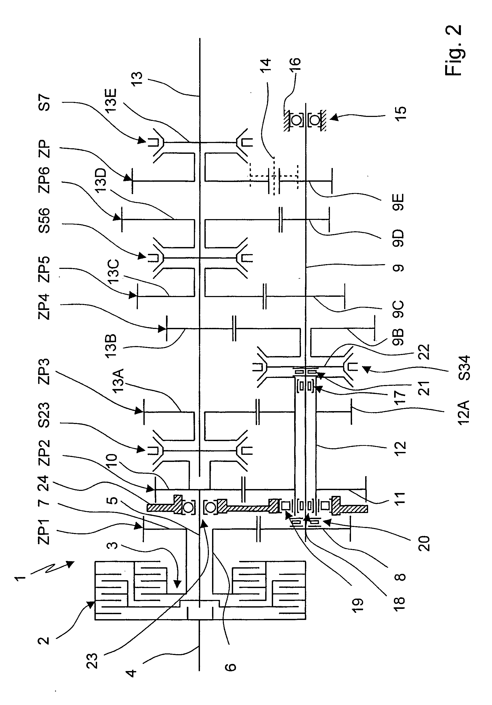
[0017]FIG. 1 shows a multi-speed transmission 1 of countershaft design, which has two load-shift elements 2, 3 on the side of the gearbox input, via which a torque applied via an engine shaft 4 can be selectively conducted to a main gearbox input shaft 5 or a second gearbox input shaft 6 arranged concentrically with respect to the main gearbox input shaft 5 and arranged thereon and executed as a hollow shaft.

[0018] The second load-shift element 3 is arranged radially within the first load-shift element 2, so that the mult-ispeed transmission 1 has a shorter length in the axial direction than with the load-shift elements arranged side by side, while the radially telescoping arrangement of the load-shift elements 2, 3, shown in FIG. 1, enlarges the dimensions of the multi-speed transmission 1 at the gearbox input in peripheral direction, in comparison with the load-shift elements arranged side by side.

[0019] The second gearbox input shaft, configured as hollow shaft or the hollow ge...


PUM


Abstract

A multi-speed transmission of countershaft design having a main countershaft and a hollow countershaft arranged concentrically and having likewise two load-shift elements. A first half of the shift elements is connected with a drive unit and a second half of the shift elements is connected to a gearbox input shaft. The gearbox input shafts and countershafts are mounted in a housing and connected to gear wheels, which intermesh in pairs as gear wheel pairs and can be connected or disconnected in order to reduce the overall gear ratio in the power flow. The main countershaft is mounted directly on the housing in the area of its first end and in the hollow countershaft in the area of its second end. The hollow countershaft is mounted in the housing in the area of its end that faces toward the end of the main countershaft that is mounted in the hollow countershaft.

Description

[0001] This application claims priority from German Application No. 10 2004 043 387.9 filed Sep. 8, 2004. FIELD OF THE INVENTION [0002] The invention concerns a multi-speed transmission of countershaft design, in particular a double clutch transmission. BACKGROUND OF THE INVENTION [0003] A six-speed double clutch transmission is known from DE 43 30 170 C2, which is configured with a so-called double clutch on the side of the gearbox input, which consists of two friction-locked shift elements. A drive torque of a drive motor that is applied on a motor shaft according to a transmission capacity adjusted in the respective shift elements is conducted to a first main gearbox input shaft or to a second gearbox input shaft mounted on the main gearbox input shaft and configured as a hollow shaft. The two gearbox input shafts are connected torsion-resistant to a respective gear wheel and these gear wheels mesh, in turn, with gear wheels that are respectively connected torsion-resistant to a ...

Claims


Application Information

Patent Timeline
Patent Type & Authority Applications(United States)
IPC IPC(8): F16H3/08
CPCF16H3/006F16H2003/0933Y10T74/19223Y10T74/19233Y10T74/19219Y10T74/19288
Inventor GUMPOLTSBERGER, GERHARDPATZNER, JENS
Owner ZF FRIEDRICHSHAFEN AG
Why Eureka
Try Eureka