
Plasma spray apparatus

a technology of spray apparatus and plasma, which is applied in the direction of electron beam welding apparatus, arc welding apparatus, coating, etc., can solve the problems of arc generated between the electrodes, affecting the service life of the apparatus, and requiring a long time and significant manpower

Inactive Publication Date: 2006-03-09
SHIMAZU KOGYO YUGENKAISHA
View PDF20 Cites 28 Cited by
  • Summary
  • Abstract
  • Description
  • Claims
  • Application Information

AI Technical Summary

Benefits of technology

[0015] As will be readily understood by those of ordinary skill in the art, the invention further contemplates methods employing a novel plasma spray apparatus as described herein. These methods include novel methods of thermal spraying, methods of forming a plasma spray using a selected working medium and/or spray medium, methods of forming and projecting a plasma spray to produce a surface treatment on an object or surface, and methods for producing products by forming

Problems solved by technology

Accordingly, because the structure of the plasma spray apparatus is very complicated, maintaining and servicing the apparatus requires an extremely long time and significant manpower.
Generally, in a plasma spray apparatus, the arc generated between the electrodes causes damage, particularly at the anode side.
Damage to the anode causes the trajectory of the ejected spray material to change.
That is, the spray material, which was not heated and melted satisfactorily, just flies away all around without being used as the material for the surface finishing; thus the material is consumed in vain.
Accordingly, the complexity of the structure renders it prone to frequent failures.
Thus, as with the plasma spray device described in Japanese Unexamined Patent Application Publication No. 60-129156, significant manpower and a long time are required for assembling, manufacturing and maintenance service.
Recently, the price of the spray materials including such ceramics and the like has been increasing.
However, when an expensive spray material is used, in addition to the increase of the quality of surface, the yield ratio also has to be increased.

Method used


Image

  • Plasma spray apparatus
  • Plasma spray apparatus
  • Plasma spray apparatus

Examples


Embodiment Construction

[0030] The following discussion is presented to enable a person skilled in the art to make and use the invention. Various modifications to the exemplified embodiments described herein will be readily apparent to those skilled in the art, and the generic principles herein may be applied to other embodiments and applications without departing from the spirit and scope of the present invention as defined by the appended claims. Thus, the present invention is not intended to be limited to the embodiments shown, but is to be accorded the widest scope consistent with the principles and features disclosed herein.

[0031] The inventor of the present invention investigated various aspects to improve previously-described plasma spray apparatus. As a result, the inventor found that a reason why four jet ports were previously determined to be necessary for working medium transformed into plasma is because the spray material must be carefully enclosed and heated.

[0032] Accordingly, an object of ...


PUM

PropertyMeasurementUnit
Fractionaaaaaaaaaa
Fractionaaaaaaaaaa
Lengthaaaaaaaaaa

Abstract

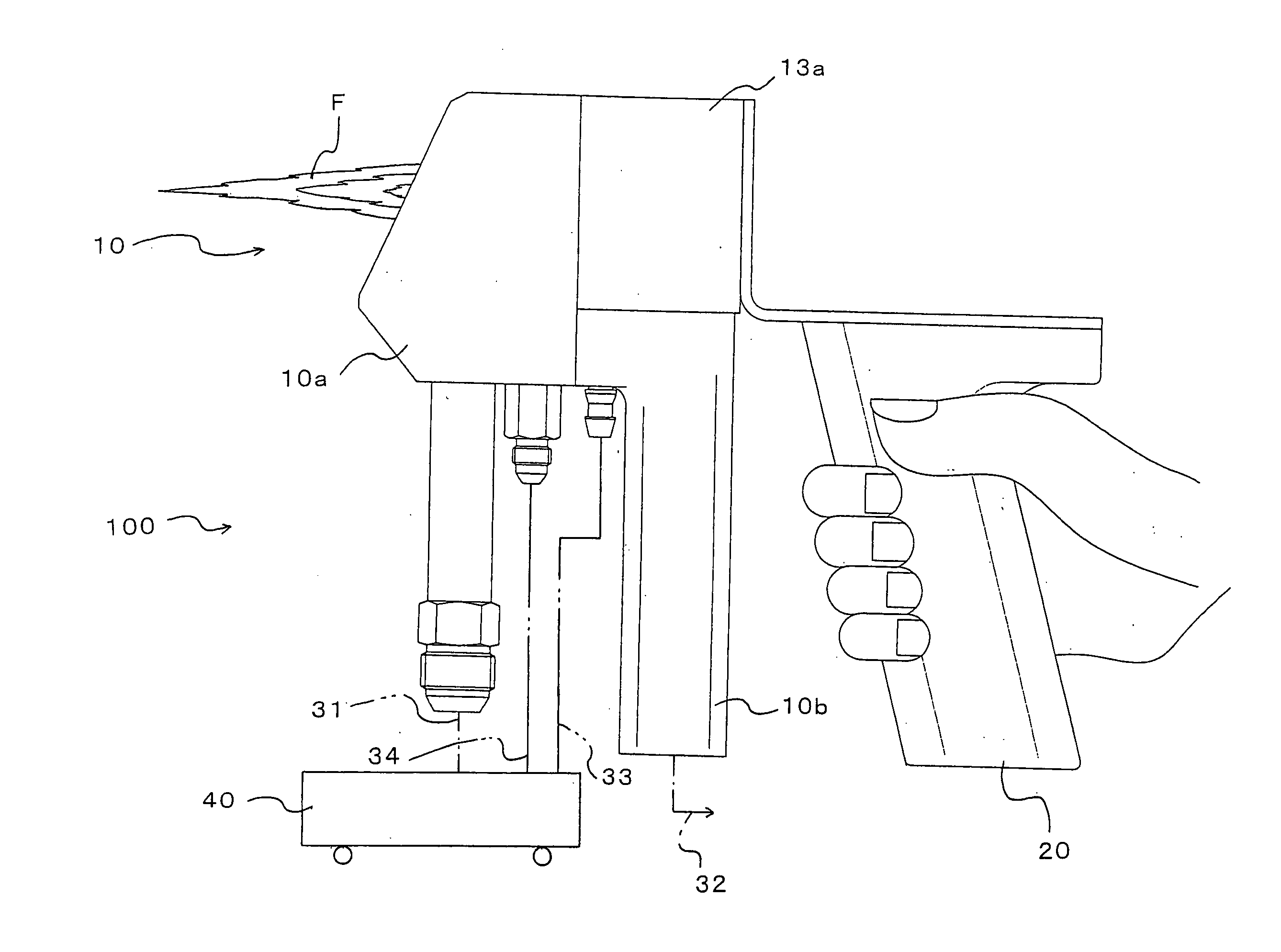
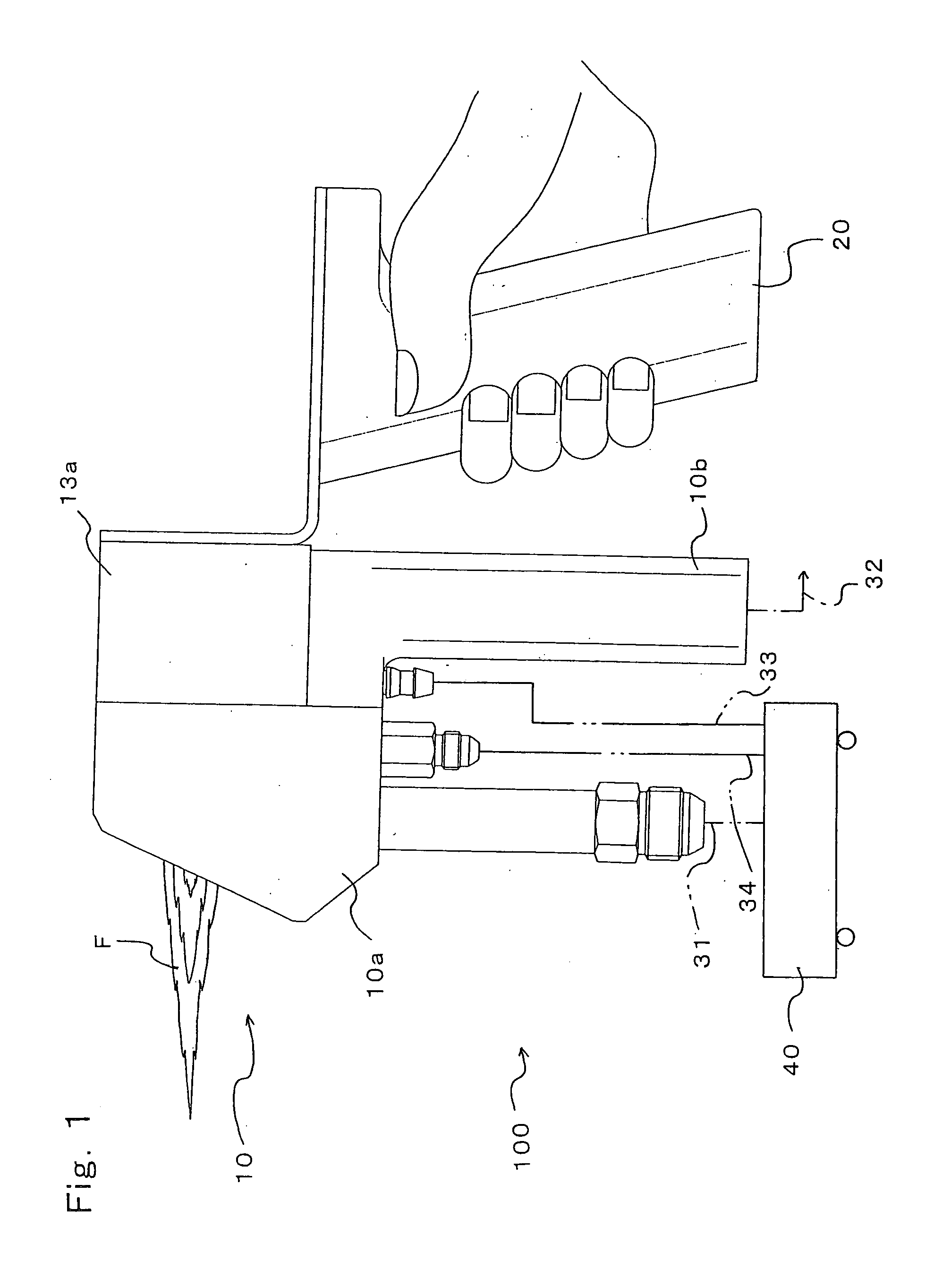
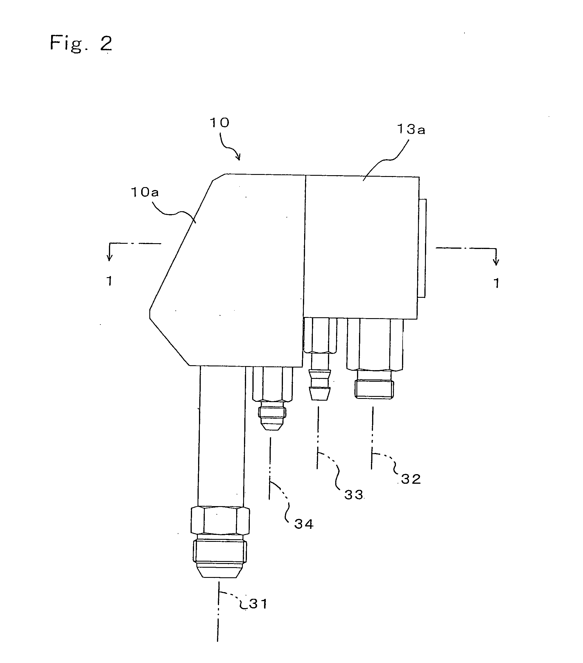
To provide a plasma spray apparatus, having a reduced number of jet ports for the working medium transformed into plasma, resulting in a simplified structure thereof, and even when the trajectory of the working medium becomes misaligned, the apparatus remains capable of producing a plasma flame that can properly melt the spray material; thus, the spray material can be used effectively. Two jet paths in the plasma spray apparatus are formed at both sides of one supply port for spray material 17 and are arranged so that the axial directions cross each other at the outside of the nozzle anode 11; two cathodes 13 are disposed inside the two jet paths 12; and the openings of the jet paths 12 are formed into elongated holes so that the center lines thereof are parallel to each other and the areas thereof are the same.

Description

FIELD OF THE INVENTION [0001] The present invention relates to a plasma spray apparatus that transforms a working medium into plasma by means of an arc generated between the anode and the cathode, and after melting the spray material by means of working medium transformed into the plasma, accelerates and ejects the melted spray material onto an object to be treated, to carry out “thermal spraying”, which is a kind of surface finishing treatment. BACKGROUND OF THE INVENTION [0002] When finishing a surface by “thermal spraying”, metals and ceramics can be used as the spray material, and a finished surface of extremely high quality can be obtained. Accordingly, various kinds of methods and apparatus have been developed. The inventor of the present invention also has proposed various related inventions, as set forth for example in Japanese Unexamined Patent Application Publication No. 60-129156, and Japanese Examined Patent Application Publication No. 4-55748. Other publications pertine...

Claims


Application Information

Patent Timeline
IPC IPC(8): B23K9/00B23K9/02
CPCC23C4/127B23K15/0093C23C4/134
Inventor SHIMAZU, TADAHIRO
Owner SHIMAZU KOGYO YUGENKAISHA
Learn More