Coating Systems for Protection of Substrates Exposed to Hot and Harsh Environments and Coated Articles

a coating system and substrate technology, applied in the direction of superimposed coating process, natural mineral layered products, light and heating apparatus, etc., can solve the problems of affecting the service life of the tbc system, and affecting the effect of the coating

Inactive Publication Date: 2011-06-23
GENERAL ELECTRIC CO
View PDF13 Cites 44 Cited by
  • Summary
  • Abstract
  • Description
  • Claims
  • Application Information

AI Technical Summary

Benefits of technology

[0007]The above-mentioned needs may be met by exemplary embodiments that provide coating systems for components utilized in hot and harsh climates. The protected component may be suitable for use in a high-temperature environment such as the hot section of a gas turbine engine. Exemplary embodiments may be particularly useful in preventing or mitigating the effects of CMAS infiltration.

Problems solved by technology

The service life of a TBC system is typically limited by a spallation event brought on by thermal fatigue.
In addition to the CTE mismatch between a ceramic TBC and a metallic substrate, spallation can occur as a result of the TBC structure becoming densified with deposits that form on the TBC during gas turbine engine operation.
The loss of the TBC results in higher temperature exposure for the underlying substrate, accelerating oxidation and poor creep and low cycle fatigue performance.

Method used


Image

  • Coating Systems for Protection of Substrates Exposed to Hot and Harsh Environments and Coated Articles
  • Coating Systems for Protection of Substrates Exposed to Hot and Harsh Environments and Coated Articles
  • Coating Systems for Protection of Substrates Exposed to Hot and Harsh Environments and Coated Articles

Examples


example 1

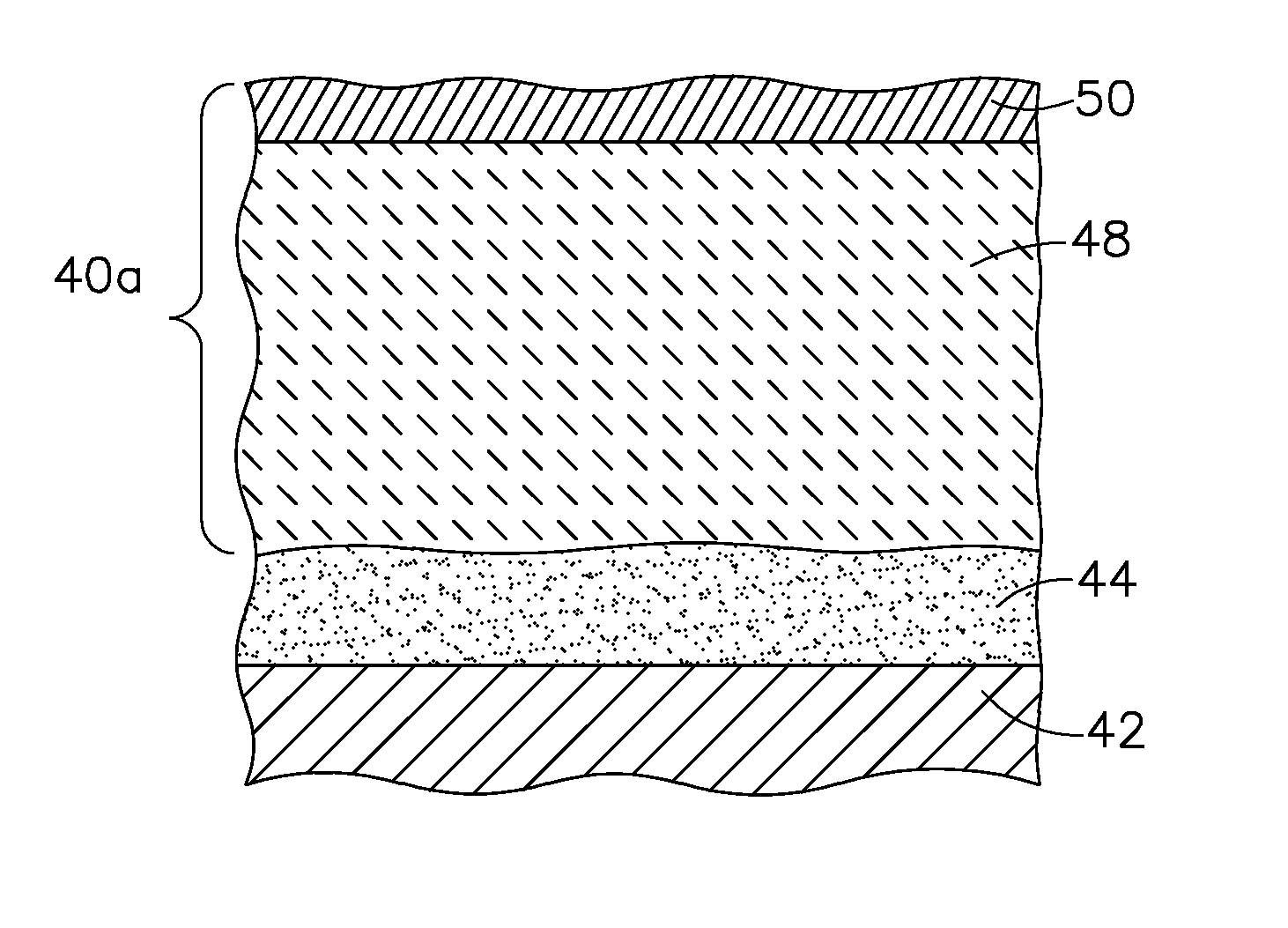
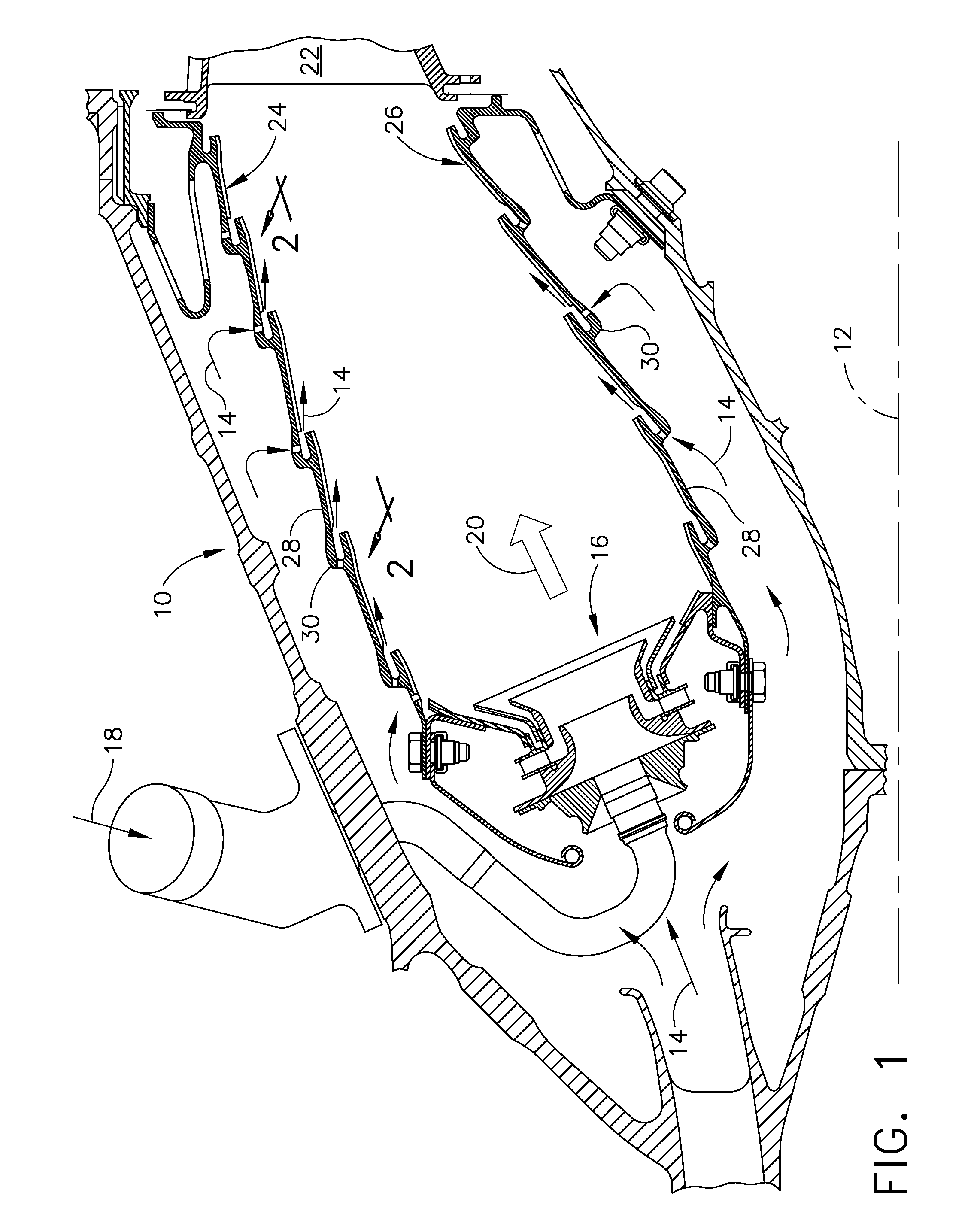
[0046]A multi-layered coating system on a substrate (or on a bond coated substrate) includes an inner ceramic layer consisting substantially of yttria stabilized zirconia having a thickness of from about 127 to about 254 microns (about 5 to about 10 mils). A first intermediate alumina-containing layer overlying the inner layer consists substantially of alumina or alumina and up to about 50% by weight titania deposited by an HVOF technique to a thickness of from about 25 to about 51 microns (about 1 to 2 mils). A first intermediate ceramic layer overlying the first intermediate alumina-containing layer consists substantially of yttria stabilized zirconia having a thickness of from about 127 to about 254 microns (about 5 to about 10 mils). An outer alumina-containing layer overlying the first intermediate ceramic layer consists substantially of alumina or alumina and up to about 50% by weight titania, deposited to a thickness of about 25 to about 51 microns (about 1-2 mils) utilizing ...

example 2

[0047]A multi-layered coating system on a substrate (or a bond coated substrate) includes an inner ceramic layer consisting substantially of yttria stabilized zirconia having a thickness of from about 127 to about 254 microns (about 5 to about 10 mils). A first intermediate alumina-containing layer overlying the inner ceramic layer includes an air plasma sprayed graded layer having a thickness of from about 127 to about 254 microns (about 5-10 mils) 50% by weight alumina (or alumina / titania) the balance yttria stabilized zirconia and increasing the content of alumina (or alumina / titania) in the intermediate alumina-containing layer. An outer alumina or alumina / titania layer is applied using an HVOF technique to a thickness of from about 25 to about 51 microns (about 1-2 mils).


PUM

PropertyMeasurementUnit
thicknessaaaaaaaaaa
thicknessaaaaaaaaaa
thicknessaaaaaaaaaa

Abstract

Coating system for reducing CMAS infiltration of substrates includes at least an inner ceramic layer and an outer alumina-containing layer. The outer layer includes up to 50 percent by weight titania. Additional ceramic layers and alumina-containing layers may be provided. The coating may be used for gas turbine engine components. Deposition techniques for the coating layers may depend on the end use of the component. Coated articles include a substrate, an optional bond coat on the substrate and a coating over the bond coat or on at least a portion of the substrate in the absence of a bond coat. The inner ceramic layer(s) exhibit a microstructure indicative of a deposition technique selected from thermal spray, physical vapor deposition, and suspension plasma spray, whereas the outer alumina-containing layer exhibits a microstructure indicative of suspension plasma spray, solution plasma spray, and a high velocity oxygen fuel spray.

Description

CROSS REFERENCE TO RELATED APPLICATIONS[0001]This application claims priority and benefit of U.S. Provisional Patent Application Ser. No. 61 / 288,476, filed Dec. 21, 2009; U.S. Provisional Patent Application Ser. No. 61 / 288,486, filed Dec. 21, 2009; and U.S. Provisional Patent Application Ser. No. 61 / 288,490, filed Dec. 21, 2009, the disclosures of which are incorporated herein by reference in their entirety.BACKGROUND OF THE INVENTION[0002]This invention generally relates to coating systems for components exposed to high temperatures, such as the hostile thermal environment of a gas turbine engine and articles coated with such coating systems. More particularly, this invention is directed to a coating system comprising an alumina-containing layer applied over a ceramic thermal barrier coating layer.[0003]The efficiency of the engine is directly related to the temperature of the combustion gases. High temperature capability superalloy metals may be utilized for those components expos...

Claims


Application Information

Patent Timeline
Patent Type & Authority Applications(United States)
IPC IPC(8): B32B7/02B32B9/04B32B5/00
CPCC23C4/105F23M2900/05003F23M2900/05004F23R3/007F23R2900/00018Y10T428/24967C23C28/3215C23C28/345C23C28/3455C23C28/36Y10T428/263Y02T50/67C23C4/11Y02T50/60
Inventor NAGARAJ, BANGALOREFEW, TERRY LEEMCCAFFREY, TIMOTHY P.L'HEUREUX, BRIAN P.
Owner GENERAL ELECTRIC CO
Why Eureka
Try Eureka