Linear actuator

a linear actuator and actuator technology, applied in the direction of positive displacement liquid engine, magnet body, piston pump, etc., can solve the problems of large magnetic gap, expensive stator magnet m, and difficult compactness of apparatus, so as to reduce the consumption of power

Inactive Publication Date: 2006-03-09
NIPPON PULSE MOTOR CO LTD
View PDF13 Cites 36 Cited by
  • Summary
  • Abstract
  • Description
  • Claims
  • Application Information

AI Technical Summary

Benefits of technology

[0013] This means not only that the apparatus as a whole can be made compact, but also that energizing control is possible for each coil, and that synchronous energizing, different mode energizing with differing energizing strength and energizing of only one coil etc. can be carried out. It is therefore also possible to reduce the consumed power required to maintain a stop position using excitation and propagation movement of strong magnetic thrust towards the moveable part is possible. It is possible to provide a movement stroke with a long stroke as well as a short stroke in accordance with usage of the actuator.

Problems solved by technology

As a result, it is difficult to set the magnetic gap to be large (5 to 30 mm) so as to vibrate a long stroke.
This makes making the apparatus compact difficult.
Also, an expensive stator magnet M is required.
It means that the apparatus itself is large and cannot be make cheaply, and also causes the range of applications to be limited.

Method used


Image

  • Linear actuator
  • Linear actuator
  • Linear actuator

Examples


Embodiment Construction

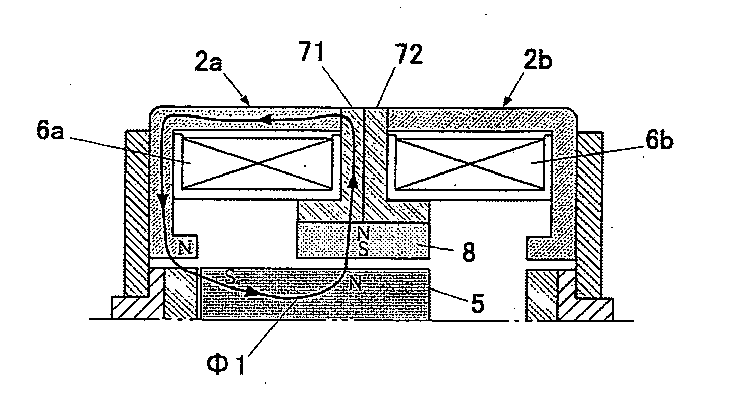
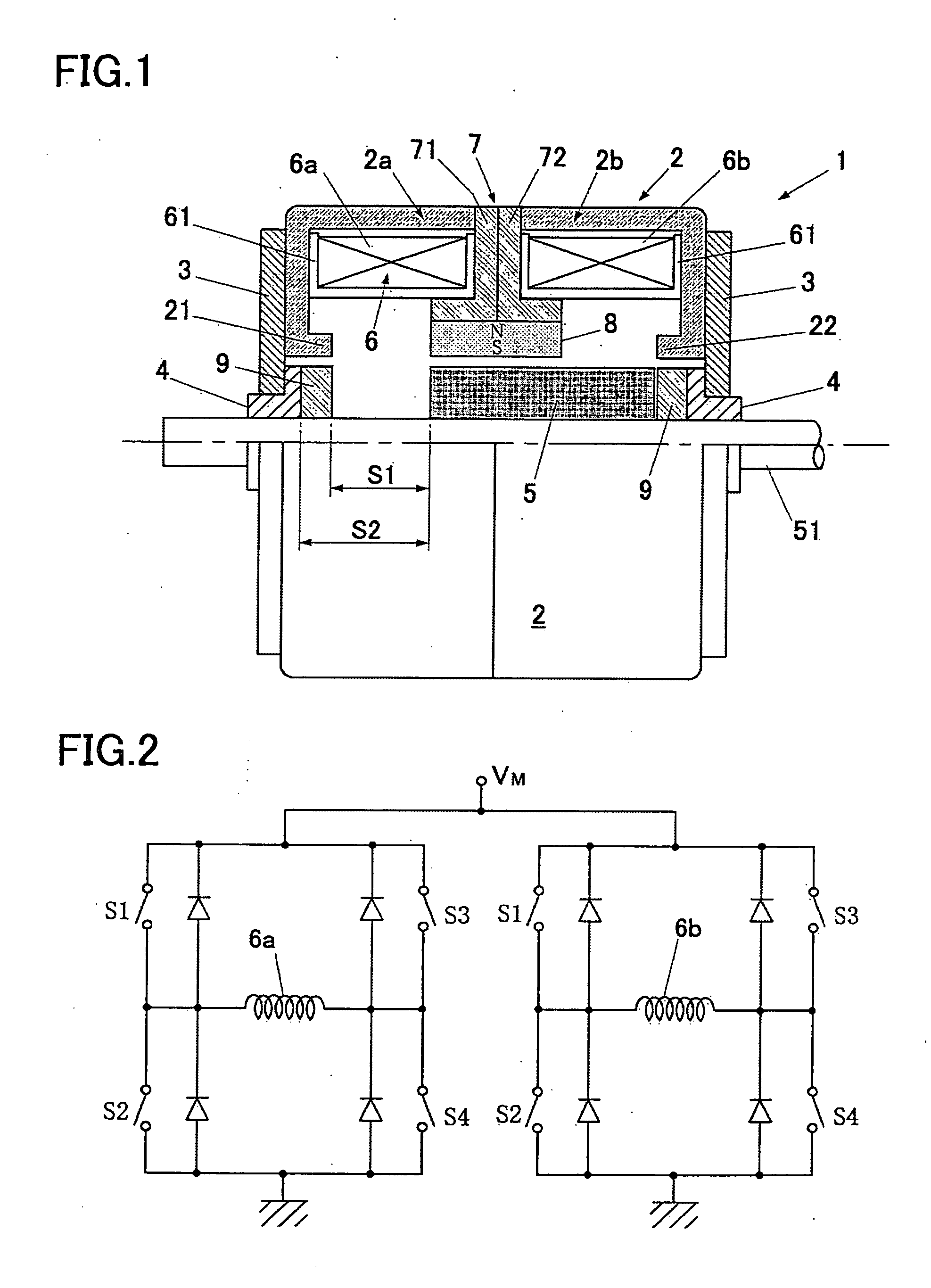
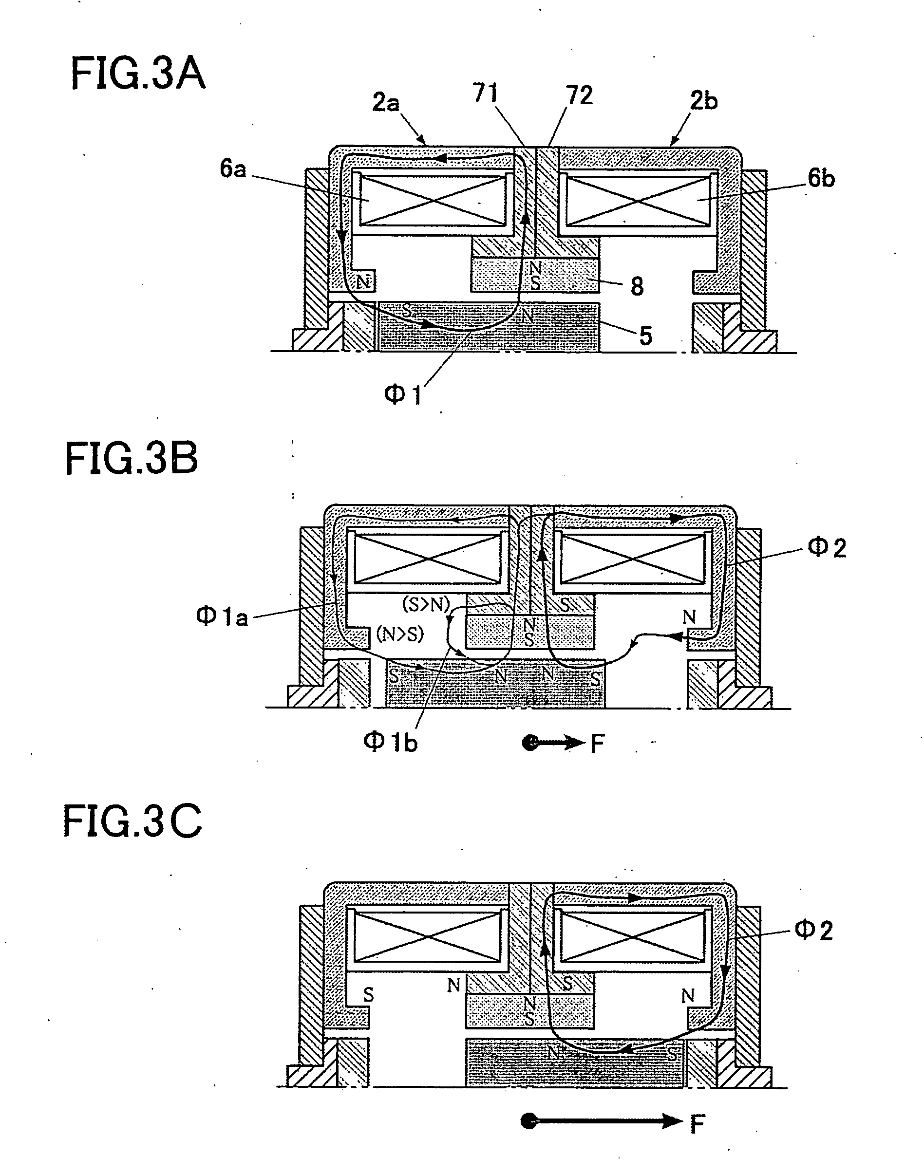
[0020] The following is a detailed description based on the drawings of a linear actuator exemplifying a preferred embodiment of the present invention. FIG. 1 is a cross-sectional structural view of half of a linear actuator, and FIG. 2 is a view illustrating a coil circuit. As shown in FIG. 1, a linear actuator 1 is comprised of a yoke 2 made of iron or magnetic stainless steel etc. forming a cylindrical body and magnetic path for the actuator body, a flange 3 arranged to either side of the yoke 2, a bearing 4 provided at the center of flange 3, and a moveable part 5 having a shaft section 51 that is provided at the bearings 4 arranged on both sides of the yoke 2 so as to be moveable in an axial direction. A coil 6 (6a, 6b) wound around a coil bobbin 61 made of resin provided at an inner wall and a stator magnet 8 composed of a permanent magnet provided between the coil 6 and the moveable part 5 are also arranged within the yoke 2.

[0021] The coils 6 is provided split symmetrically...


PUM


Abstract

The present invention is directed to provide a linear actuator capable of propagating magnetic force of a stator magnet within a yoke in a smooth manner so as to form a superior magnetic path. A linear actuator is provided with a moveable part facing a stator magnet provided together with a coil within a yoke, with both magnetic pole pieces of the yoke being exited to an S pole and an N pole respectively by switching of energizing of the coil so as to subject the moveable part to thrust and bring about reciprocal driving. According to the present invention, the coil is divided into split coils so as to retain excitation function, and a magnetic path body for connecting the stator magnet and the yoke is provided between the split coils. Magnetic force of the stator magnet is transmitted to the yoke via the magnetic path body.

Description

TECHNICAL FIELD [0001] The present invention relates to an electromagnetic linear actuator, and particularly relates to a linear actuator capable of forming a superior magnetic path within a yoke. BACKGROUND ART [0002] Typically, this type of linear actuator is used in order to cause a piston of an air compressor or a blade of a razor to continuously oscillate. These oscillations correspond to oscillation drag caused by use and it is necessary to exert a strong reciprocal driving force on a moveable part so as to cause movement. [0003] In the related art, as disclosed in U.S. Pat. No. 6,028,499, a coil and a stator magnet (permanent magnet) are arranged at the center of a yoke substantially concave in cross-section. This stator magnet and a moveable part of substantially the same width are fitted within a yoke. Inclined magnetic gaps of respective widths of 1 mm are formed between the pole pieces of the yoke, so as to bring about continuous oscillation with a short stroke of 2 mm in...

Claims


Application Information

Patent Timeline
Patent Type & Authority Applications(United States)
IPC IPC(8): H02K41/00
CPCF04B35/04H02K33/12H01F2007/1692H01F7/1615
Inventor SATO, SHUJI
Owner NIPPON PULSE MOTOR CO LTD
Why Eureka
Try Eureka