
Magnetron cooling fin

a cooling fin and magnetoelectric technology, applied in the direction of microwave heating, transit-tube circuit elements, solid-state devices, etc., can solve the problems of limited cooling efficiency improvement, and achieve the effect of improving cooling efficiency and improving the structure of the enlarged heat transfer area

Inactive Publication Date: 2006-03-09
LG ELECTRONICS INC
View PDF15 Cites 14 Cited by
  • Summary
  • Abstract
  • Description
  • Claims
  • Application Information

AI Technical Summary

Benefits of technology

[0011] The present invention is disclosed to solve the aforementioned problem in the prior art. An object of the present invention is to provide a magnetron cooling fin with an improved structure of an enlarged heat transfer area for facilitating heat transfer, thereby improving a cooling efficiency.
[0012] Another object of the present invention is to provide a magnetron cooling fin with an enhanced economical efficiency by modifying a conventional cooling fin of a magnetron to maximize the enlargement of a heat transfer area through a simple and easy manufacturing process, thereby improving cooling performance.

Problems solved by technology

However, if a magnetron with the same output needs to have a compact anode structure, there arises a problem of improvement of cooling efficiency being limited, due to a restricted heat transfer area of a cooling fin.

Method used


Image

  • Magnetron cooling fin
  • Magnetron cooling fin
  • Magnetron cooling fin

Examples


Embodiment Construction

[0025] Hereinafter, a magnetron cooling fin according to a preferred embodiment of the invention will be described in detail with reference to the accompanying drawings.

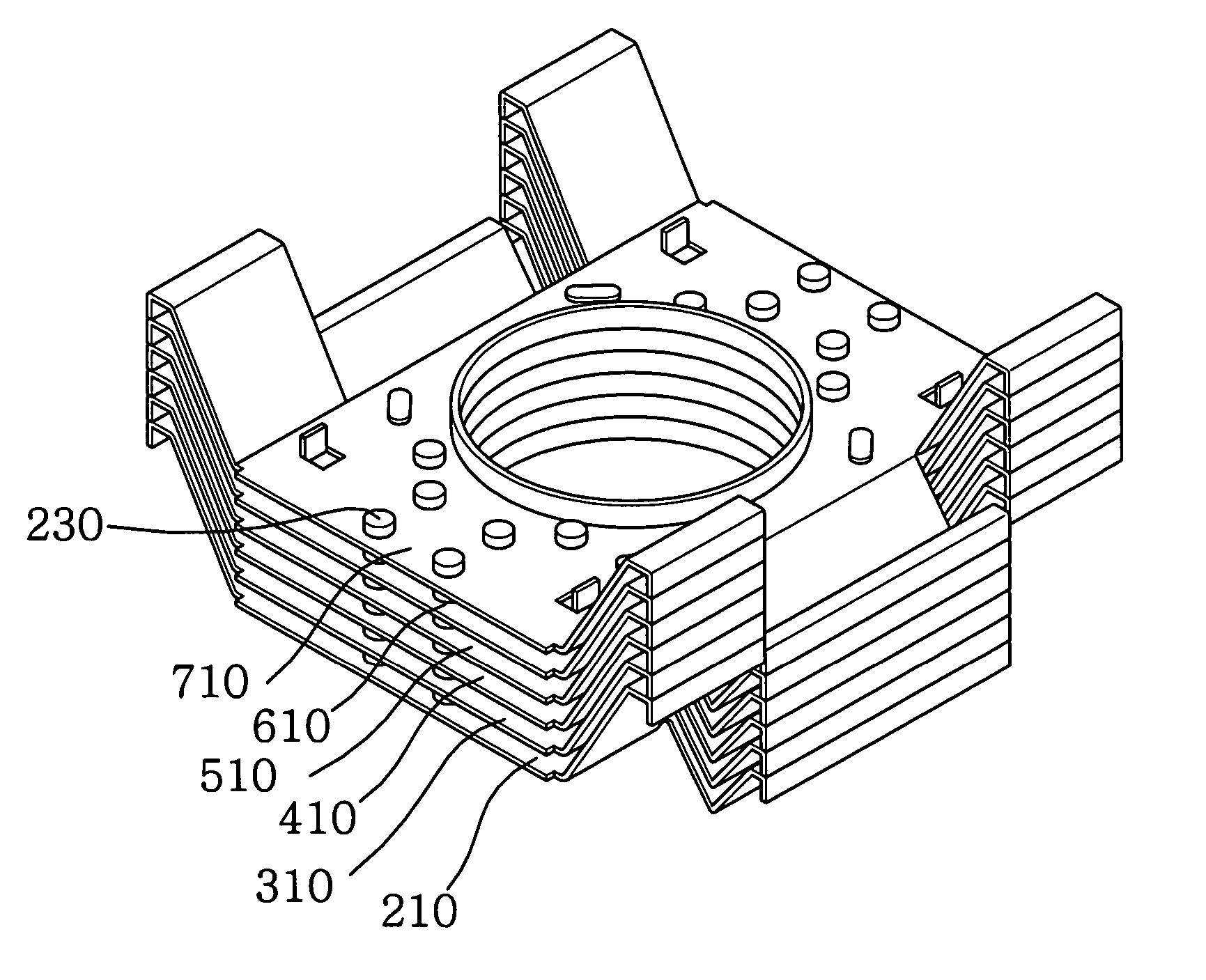
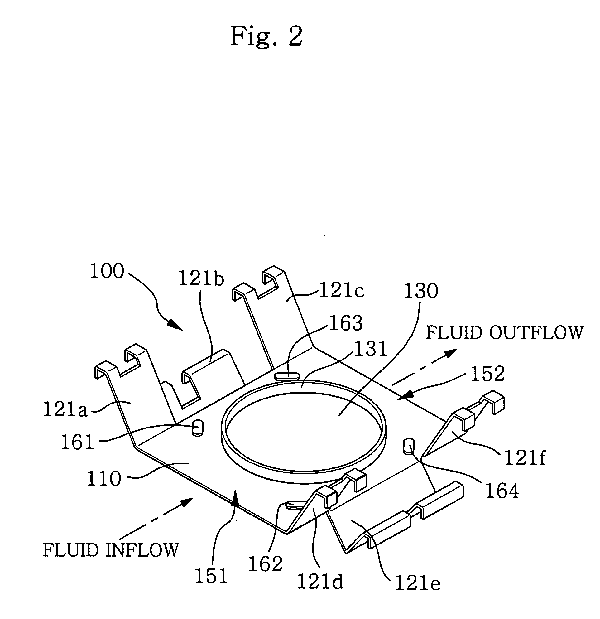
[0026] Referring to FIG. 3, a magnetron cooling fin (200) according to the present invention includes a planar body (210) with a boss-type through-hole (210a) through which an anode penetrates to be coupled therein, a plurality of coupling pieces (221. 222. 223. 224. 225. and 226) outwardly extending and bent at edges of the planar body (210), and a plurality of turbulence-promoting protrusions (230) arranged in a predetermined pattern while protruding from one side of the planar body (210).

[0027] Preferably, in the magnetron cooling fin thus constructed according to the present invention, the turbulence-promoting protrusions (230) protrude in the same direction as that of a projection (211) protruding from the periphery of the boss-type through-hole (210a).

[0028] Meanwhile, the turbulence-promoting protrusions (2...


PUM


Abstract

A magnetron cooling fin is disclosed, characterized in that a plurality of turbulence-promoting protrusions are provided on one side of a planar body that has a boss-type through-hole in which an anode is coupled and a plurality of coupling pieces outwardly extending and bent at edges of the planar body, whereby, with inflow air undergoing flow separation at top ends of the turbulence-promoting protrusions and coming again into contact with the planar body, an existing temperature boundary gets thinned and a friction coefficient gets increased, thereby improving a heat transfer rate and an cooling efficiency.

Description

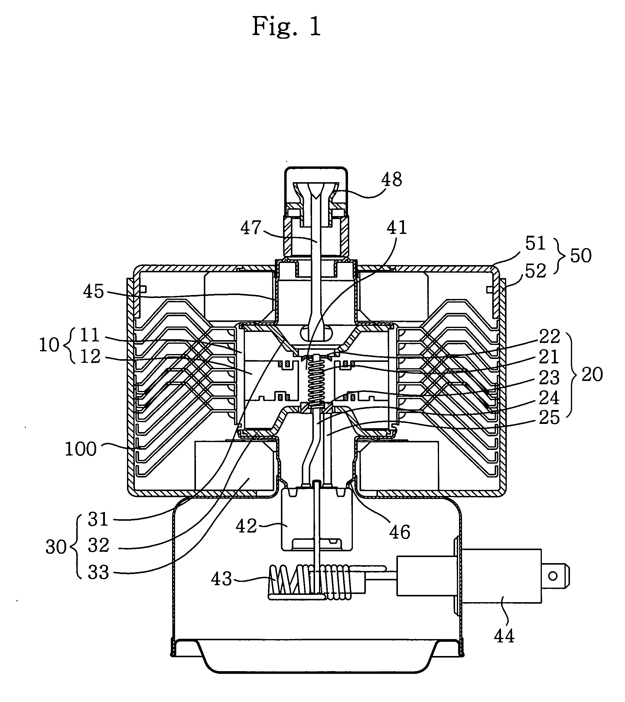
BACKGROUND OF THE INVENTION [0001] 1. Field of the Invention [0002] The present invention relates to a magnetron cooling fin, and more particularly, to a magnetron cooling fin structured to have an enlarged heat transfer area to thereby improve a cooling efficiency. [0003] 2. Description of the Related Art [0004] Generally, a magnetron is used as a heat source for heating a target in such a manner that electrons discharged from a cathode upon application of electric power thereto generate radio frequency energy of about 2,450 MHz by means of electric and magnetic fields and the generated energy is then output via an antenna. Such a magnetron comprises an anode unit (10), a cathode unit (20), and a magnetic unit (30), as shown in FIG. 1. [0005] The anode unit (10) comprises an anode cylinder (11), and a plurality of vanes (12) radially formed on an inner surface of the anode cylinder (11). The cathode unit (20) comprises a filament (21), end shields (22) and (23), a center lead (24),...

Claims


Application Information

Patent Timeline
IPC IPC(8): H01J25/50
CPCH01J23/005H05B6/72H01L2924/0002H01L2924/00H01J23/16
Inventor LEE, JONG SOOLEE, YONG SOO
Owner LG ELECTRONICS INC
Learn More