System for enhanced detection of a target

a target detection and target technology, applied in the field of enhanced detection systems, methods and devices, can solve the problems of cost differential, cost-prohibitive, invasive hardware modifications, including the addition of components and signal paths, and the ability to achieve the effect of enhancing the detection effect, and achieving the effect of cost-prohibitive, cost-prohibitive, and cost-prohibitiv

Inactive Publication Date: 2006-03-09
SYSTEM PLANNING CORPORATION
View PDF9 Cites 53 Cited by
  • Summary
  • Abstract
  • Description
  • Claims
  • Application Information

AI Technical Summary

Benefits of technology

[0019] Some embodiments of the system include the radar device, which is preferably a non-coherent radar device. Some embodiments of the system include a display for showing the discriminated target substantially free of clutter. The target preferably includes at least a portion of a watercraft and may include a submarine periscope. In some embodiments of the system, the target comprises a human, a land vehicle, or both. The clutter preferably comprises at least one of terrain clutter, rain clutter, and discrete clutter, and more preferably comprises sea clutter. Some embodiments of the system are substantially free of a coherent radar device.

Problems solved by technology

While amplitude-based detection is suitable for some circumstance, it is not preferable for all circumstances particularly when the target is small, when there is a large amount of clutter relative to the target strength, or both.
The magnitude of the cost differential is due, at least in part, to the use of costly transmitter / receiver technologies that are used to obtain phase coherence.
Invasive hardware modifications, including the addition of components and signal paths, may be cost-prohibitive.
There are no known examples of a system for non-invasive modifications that provide coherence of return pulses received by a non-coherent radar device.

Method used


Image

  • System for enhanced detection of a target
  • System for enhanced detection of a target
  • System for enhanced detection of a target

Examples


Embodiment Construction

[0051] In describing a preferred embodiment of the invention illustrated in the drawings, specific terminology will be used for the sake of clarity. However, the invention is not intended to be limited to the specific terms so selected, and it is to be understood that each specific term includes all technical equivalents which operate in a similar manner to accomplish a similar purpose.

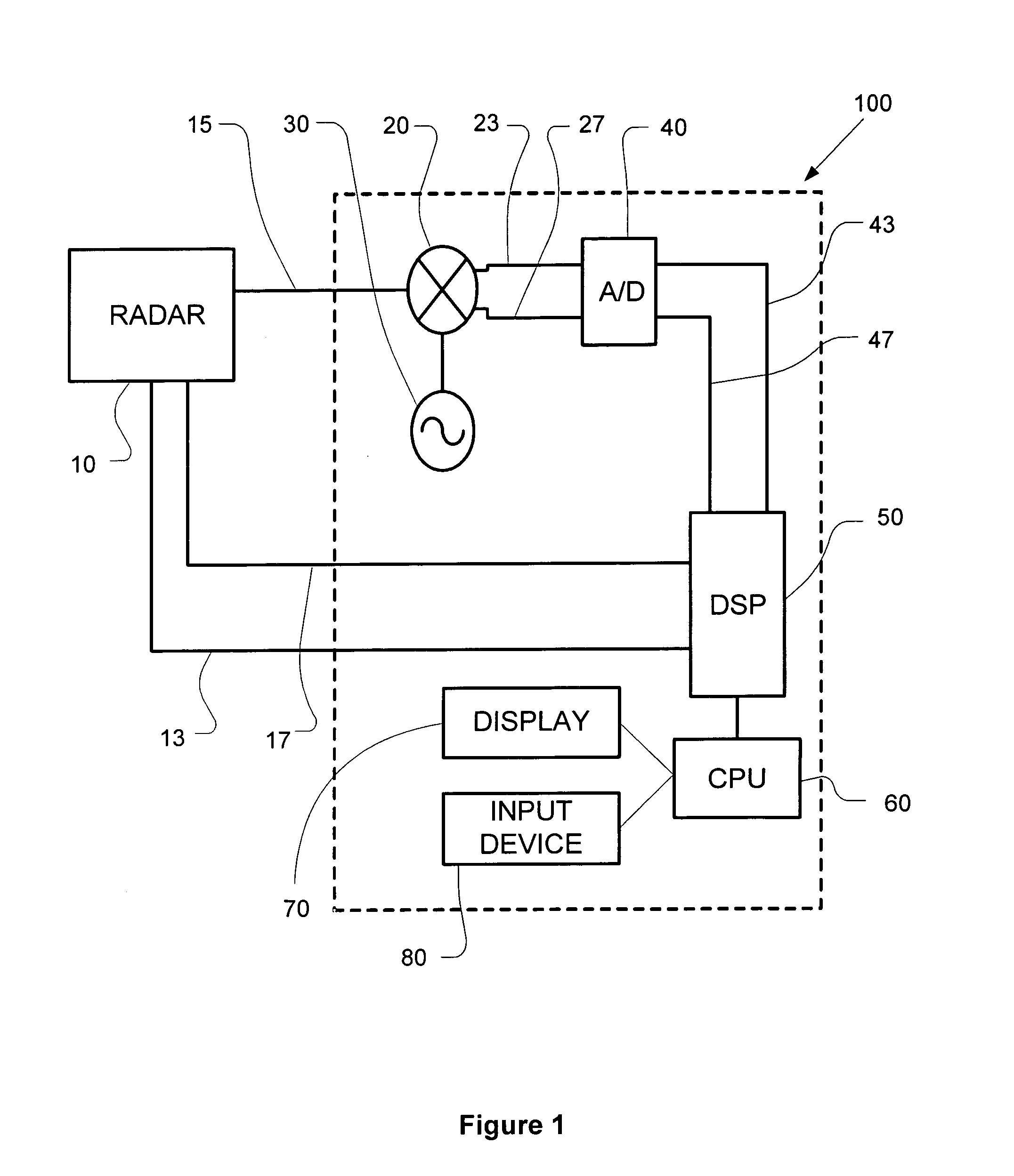
[0052] With principal reference to FIG. 1, an enhanced detection system is designated generally 100 and shown coupled to a radar device 10. In preferred embodiments, enhanced detection system 100 comprises a mixer 20, a coherent oscillator 30, an analog-to-digital converter 40, a digital signal processor 50, a central processing unit 60, a display 70, and an input device 80.

[0053] Enhanced detection system 100 is suitable for cohering non-coherent radar devices, such as a magnetron-based radar device; however, embodiments of enhanced detection system 100 may also be suitable for enhancing the perfor...


PUM


Abstract

Disclosed herein is a computer-readable medium having stored thereon computer-executable instructions for providing phase-range data associated with a return pulse of a radar device and second phase-range data associated with a successive return pulse of the radar device. The computer-executable instructions are preferably also for comparing the phase-range data and the second phase-range data to obtain a difference, and for differentiating the difference. In some embodiments of the invention, the computer-executable instructions are preferably also for discriminating a target from clutter by using the differentiated difference to identify coordinates satisfying a velocity threshold associated with the clutter. Embodiments of the invention preferably enable phase-coherent operation of a non-coherent radar device by processing backscattered clutter return, and in some aspects, do so using clutter distributed in range as a reference. Related systems, methods, devices, and other embodiments are also disclosed herein.

Description

CROSS-REFERENCE TO RELATED APPLICATIONS [0001] The current application claims the benefit under 35 U.S.C. § 119(e) of U.S. provisional patent application 60 / 607,122 filed on Sep. 3, 2004, which is hereby incorporated by reference in its entirety for all purposes.BACKGROUND OF THE INVENTION [0002] 1. Field of Invention [0003] The invention disclosed herein relates generally to a system, method and device for enhanced detection of a target. More specifically, preferred embodiments of the disclosed invention relate to an enhanced detection system, method and device to discriminate a target from clutter using an existing non-coherent radar device. [0004] 2. Description of the Related Art [0005] Known magnetron-based radar devices use the amplitude information associated with an echo or return pulse in an attempt to detect a target. While amplitude-based detection is suitable for some circumstance, it is not preferable for all circumstances particularly when the target is small, when the...

Claims


Application Information

Patent Timeline
Patent Type & Authority Applications(United States)
IPC IPC(8): G01S13/534
CPCG01S13/534G01S7/2923
Inventor SIEGEL, ALAN
Owner SYSTEM PLANNING CORPORATION
Why Eureka
Try Eureka