Optical distance measuring sensor and self-propelled cleaner

a technology of optical distance measurement and self-propelled cleaner, which is applied in the direction of distance measurement, instruments, and using reradiation, can solve the problems of increasing the size of the device, poor long-term stability of the sensor device, and low responsiveness, and achieve satisfactory long-term stability and high measurement accuracy. , the effect of small or no nois

Active Publication Date: 2006-03-09
MICROSOFT TECH LICENSING LLC
View PDF5 Cites 17 Cited by
  • Summary
  • Abstract
  • Description
  • Claims
  • Application Information

AI Technical Summary

Benefits of technology

[0009] An object of the present invention is to provide an optical distance measuring sensor which generates little or no noise, has comparatively satisfactory long-te...

Problems solved by technology

However, making the infrared sensor mechanically scan the range raises a problem that noises are generated by the mechanical scanning movement and a problem that the responsiveness is comparatively low because of the mechanical scan.
This arrangement has a further problem that long-term stability of the sensor device is comparatively poor because of the required maintenance of the scan mechanism.
Using a plurality of infrared sensors has a problem that the sensor device has an increased size, so that apparatuses to be equipped with the sensor device are limited.
This arrangement has a further problem that the manufacturing cost is increased due ...

Method used


Image

  • Optical distance measuring sensor and self-propelled cleaner
  • Optical distance measuring sensor and self-propelled cleaner
  • Optical distance measuring sensor and self-propelled cleaner

Examples


Embodiment Construction

[0056] The present invention will be described in detail below by the embodiments thereof shown in the drawings.

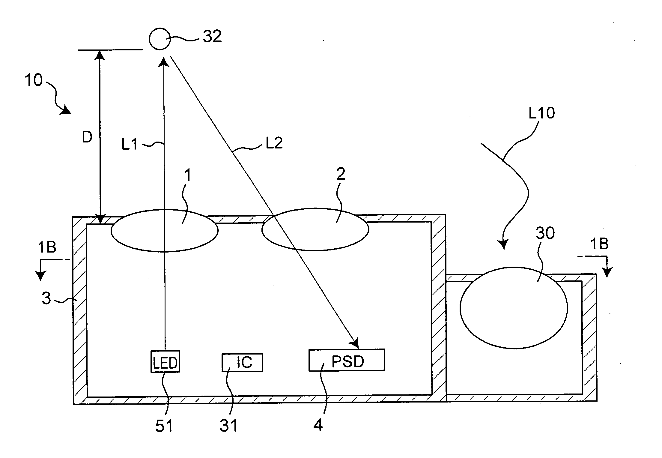
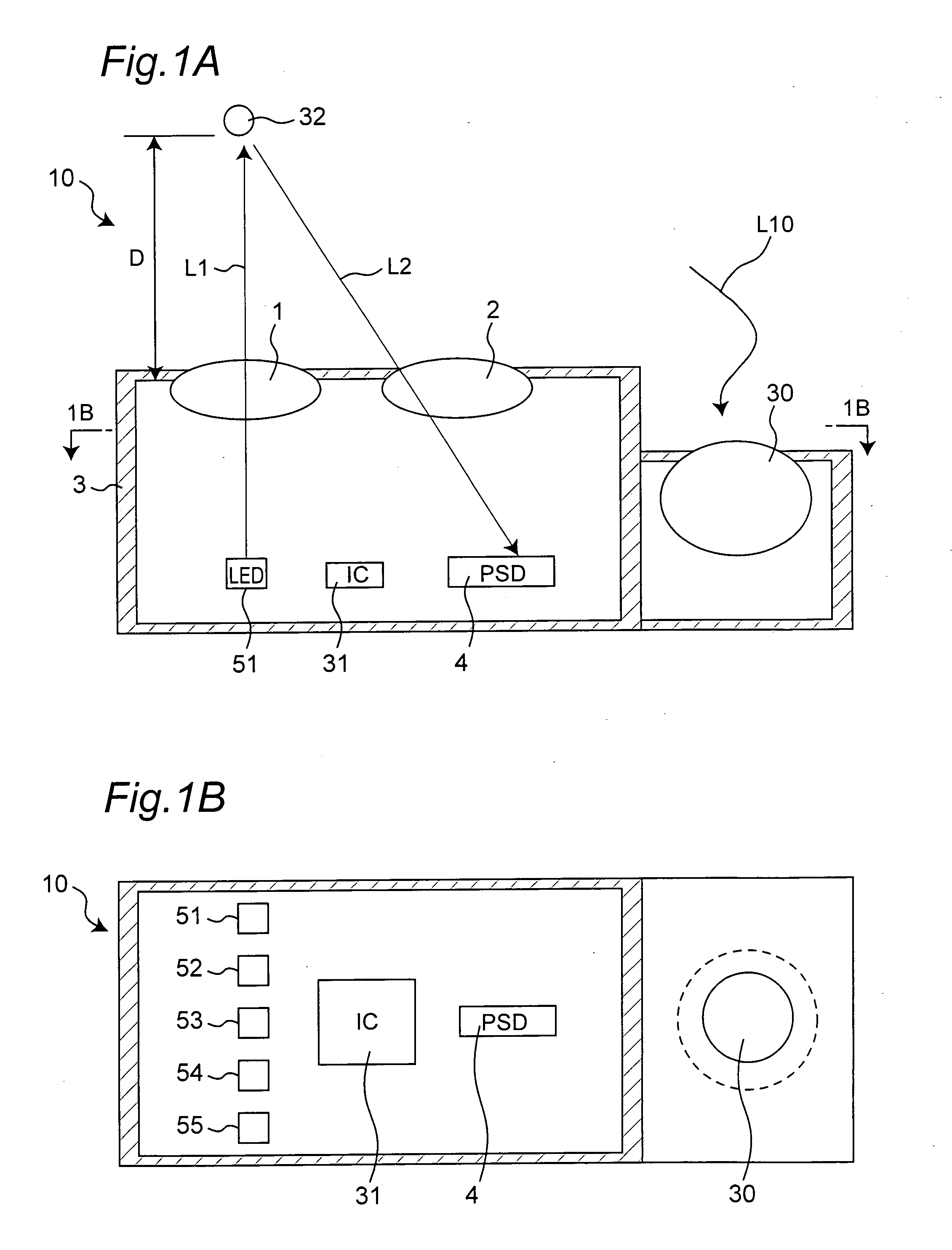
[0057]FIG. 1A is a schematic cross-sectional view showing a multi-beam distance measuring sensor as the optical distance measuring sensor of the present invention. FIG. 1B is a sectional view taken along line 1B-1B of FIG. 1A. The multi-beam distance measuring sensor 10 includes five LEDs (light emitting diodes) 51, 52, 53, 54 and 55 as light-emitting elements that emit infrared rays, and a PSD (position sensitive detector) 4 as a photodetector. One light-emitting lens 1, which receives incident light from the LEDs 51-55 and emits parallel light, is provided in a position opposite to the LEDs 51-55. The light-emitting lens 1 consists of a circular lens. A light-receiving lens 2 for condensing light from an object to be detected 32 on the PSD 4 is provided in a position roughly opposite to the PSD 4. The light-receiving lens 2 consists of a toroidal lens. The LEDs 51-55 an...


PUM


Abstract

An optical distance measuring sensor has a plurality of light-emitting elements (51-55), a light-emitting lens (1), a photodetector (4) having a light-receiving surface, a light emission driving part (31) to sequentially drive the light-emitting elements, and a distance signal outputting part (31). Light emitted from each light-emitting element passes through the light-emitting lens, then is reflected by an object (32) to be detected, and then gets incident on the light-receiving surface of the photodetector, which outputs a signal corresponding to a position of the incident light in the light-receiving surface. Upon receipt of the signal, the distance signal outputting part outputs a distance signal representing a distance to the object.

Description

[0001] This nonprovisional application claims priority under 35 U.S.C. §119(a) on Patent Application No. 2004-188091 filed in Japan on 25 Jun. 2004, the entire contents of which are hereby incorporated by reference. BACKGROUND OF THE INVENTION [0002] 1. Field of the Invention [0003] The present invention relates to an optical distance measuring sensor that detects the presence of an object in a prescribed range and a direction in which the object is located and measures a distance to the object. The present invention also relates to a self-propelled cleaner incorporating such a sensor. [0004] 2. Description of the Related Art [0005] Conventionally, pyroelectric sensors, ultrasonic sensors, reflection type infrared sensors, infrared distance measuring sensors and so on have been used as sensors intended to detect human bodies and objects, and combinations of some of those different sensors are also used. [0006] As a sensor of the kind, a sensor device including a pyroelectric sensor ...

Claims


Application Information

Patent Timeline
IPC IPC(8): G01C3/08G01B11/26G01S7/481G01S17/48G01V8/00
CPCG01C3/08G01S17/48G01S7/4814G01S7/481
Inventor MIZUO, KAZUHIROYAMAGUCHI, AKIFUMIKAWANISHI, SHINYAFUJIKAWA, ATSUO
Owner MICROSOFT TECH LICENSING LLC
Why Eureka
Try Eureka