
Fluoroscopy image verification

a fluoroscopy and image technology, applied in the field of registration of fluoroscopy images, can solve the problems of not providing solutions for reducing or minimizing registration errors, and achieve the effect of minimal invasive and negative verification

Active Publication Date: 2006-03-09
BRAINLAB
View PDF8 Cites 49 Cited by
  • Summary
  • Abstract
  • Description
  • Claims
  • Application Information

AI Technical Summary

Benefits of technology

[0008] Checking the correspondence between the artificial landmark array image shadow and the position reproduced in the navigation system enables the registration accuracy to be verified, irrespective of the patient registration and tracking equipment used. As a result, it is not necessary, within the framework of the invention, for the position of the landmark array to remain fixed or constant. Accordingly, fixing the landmark array with the aid of complicated equipment (which may be an obstruction during an operation) can be avoided. Further, since the spatial position of the landmark array can be stored, the invention enables removal or displacement of the array once the image(s) have been produced. This makes it possible, for example, to simply place the artificial landmark array on the patient while the verification recording is produced. Displacement of the patient's skin or of the landmark array (e.g., the patient is covered resulting in the array being displaced) does not have a negative effect on verification. Accordingly, it is not necessary to fixedly arrange the landmark array on an exposed bone. Thus, the invention enables a minimally invasive or even non-invasive way of verifying the registration accuracy of a fluoroscopy image.
[0009] An additional advantage is that using the artificial landmark array allows a fluoroscopy image to be verified, even when conventional verification or registration using natural landmarks is not possible or would only be possible if further invasive incisions were made. This applies, for example, to registration in soft tissue and on long bones in the intermediate area of the bone, where no useful natural landmarks can be acquired.
[0010] If an insufficient correspondence is established, it is possible to request or prompt a new fluoroscopy recording to be produced. As noted above, it is advantageous within the framework of the invention if the artificial landmark array is introduced into the radiation path of the fluoroscopy apparatus such that it can be removed after imaging. Further navigation (image-assisted surgery) can be performed with the aid of a separately provided navigation reference (reference star).

Problems solved by technology

Verification is beneficial because errors, which are undesirable, can occur in the registration process.
If, however, an insufficient number of markers are mapped, or the mapping is inaccurate, registration errors can result.
However, these references do not provide solutions for reducing or minimizing registration errors.

Method used


Image

  • Fluoroscopy image verification
  • Fluoroscopy image verification
  • Fluoroscopy image verification

Examples


Embodiment Construction

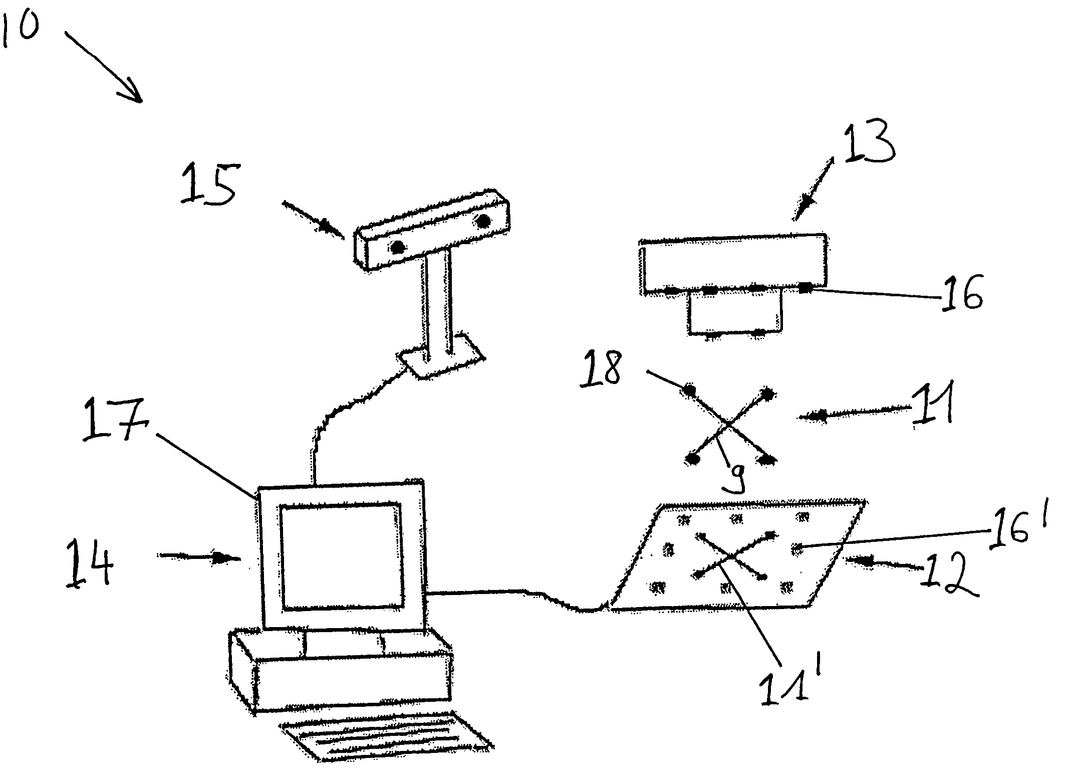
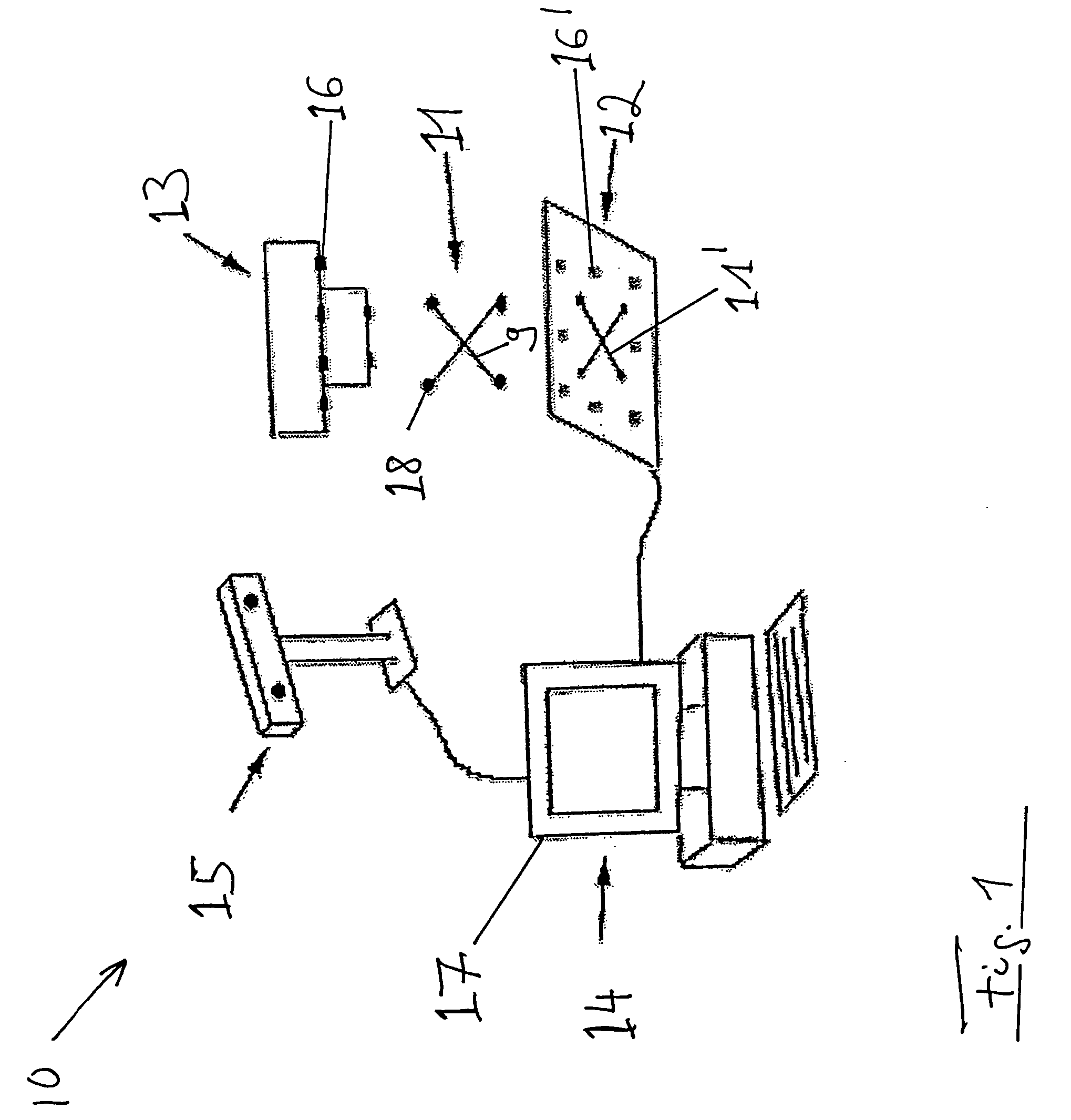
[0018]FIG. 1 schematically shows a surgical navigation system 10 that includes a computer unit 14, cameras and / or tracking unit 15 and a screen output 17. The navigation system 10 monitors a fluoroscopy device, of which only an attachment 13 is shown in FIG. 1. The attachment 13 is connected to a radiation source of the fluoroscopy apparatus (not shown). The attachment 13 includes markings 16 which, at the time a fluoroscopy recording 12 is produced, are mapped on a fluoroscopy recording 12 as markings 16′. The fluoroscopy recording 12 can be initially registered in the navigation system 10, at least in principle, using an array of different markings 16, also on different planes, pre-calibrated and known in the navigation system, e.g., the image content of the fluoroscopy recording can be spatially correlated with data provided to the navigation system 10. To this end, the spatial position of the fluoroscopy apparatus (not shown) is advantageously determined in the navigation system...


PUM


Abstract

A system and method for verifying the registration of a fluoroscopy image, wherein an artificial landmark array is introduced into a radiation path of a fluoroscopy apparatus, the landmark array being trackable by a computer assisted, medical navigation system. A fluoroscopy recording is produced with the aid of the fluoroscopy apparatus, and a spatial position of the artificial landmark array at the time the fluoroscopy recording is produced is detected and stored. The fluoroscopy recording is registered onto previously acquired body image data of the navigation system using marking points mapped on the fluoroscopy recording, wherein the marking points are maps of markings on the radiation source. Verification is based on a correspondence between an image shadow of the artificial landmark array on the fluoroscopy recording and a position of the landmark array at the time the recording was produced.

Description

RELATED APPLICATION DATA [0001] This application claims priority of U.S. Provisional Application No. 60 / 655,596 filed on Feb. 23, 2005, which is incorporated herein by reference in its entirety.FIELD OF THE INVENTION [0002] The present invention relates generally to registration of a fluoroscopy image. More particularly, the invention relates to verification of the acquisition accuracy for a fluoroscopy image that is registered within fluoroscopy-based navigation software. BACKGROUND OF THE INVENTION [0003] Fluoroscopy images, for example, can be acquired with the aid of a C-arc fluoroscopy apparatus. The images then can be transferred to a navigation system, which uses the images as a basis for image-assisted or image-guided surgery. One pre-condition for accurate image-assisted or image-guided surgery is establishing a spatial correlation between a virtual representation of a patient or body data and an actual anatomy of the patient. This process is called registration. The presen...

Claims


Application Information

Patent Timeline
IPC IPC(8): G06K9/32A61B19/00
CPCA61B6/12A61B19/52A61B19/5244A61B2019/5289A61B2019/5238A61B2019/5255A61B2017/00725A61B90/36A61B2034/2055A61B34/20A61B2090/364A61B2090/376
Inventor KRAUS, FLORIANMAIER, CHRISTIAN
Owner BRAINLAB
Learn More