Intervertebral disc prosthesis

a technology for intervertebral discs and prostheses, applied in the field of intervertebral disc prosthesis, can solve problems such as symmetrical stiffness of implants, and achieve the effects of reducing stiffness, increasing flexibility, and increasing flexibility

Inactive Publication Date: 2006-03-09
SYNTHES USA
View PDF14 Cites 127 Cited by
  • Summary
  • Abstract
  • Description
  • Claims
  • Application Information

AI Technical Summary

Benefits of technology

[0016] In yet another embodiment, the rings are arrayed peripherally, thereby offering the advantage of several peripheral sub-zones of higher and of lower stiffness.
[0017] Said elastic devices may be selected from the following materials in various embodiment modes: spiral/helical springs, elastic bellows, plas...

Problems solved by technology

However this known intervertebral disc prosthesis incurs the drawback that the stiffness of the implant is identical ...

Method used


Image

  • Intervertebral disc prosthesis
  • Intervertebral disc prosthesis
  • Intervertebral disc prosthesis

Examples


Embodiment Construction

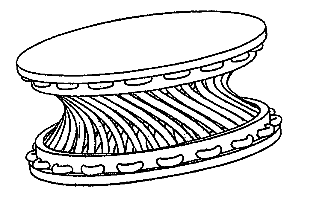
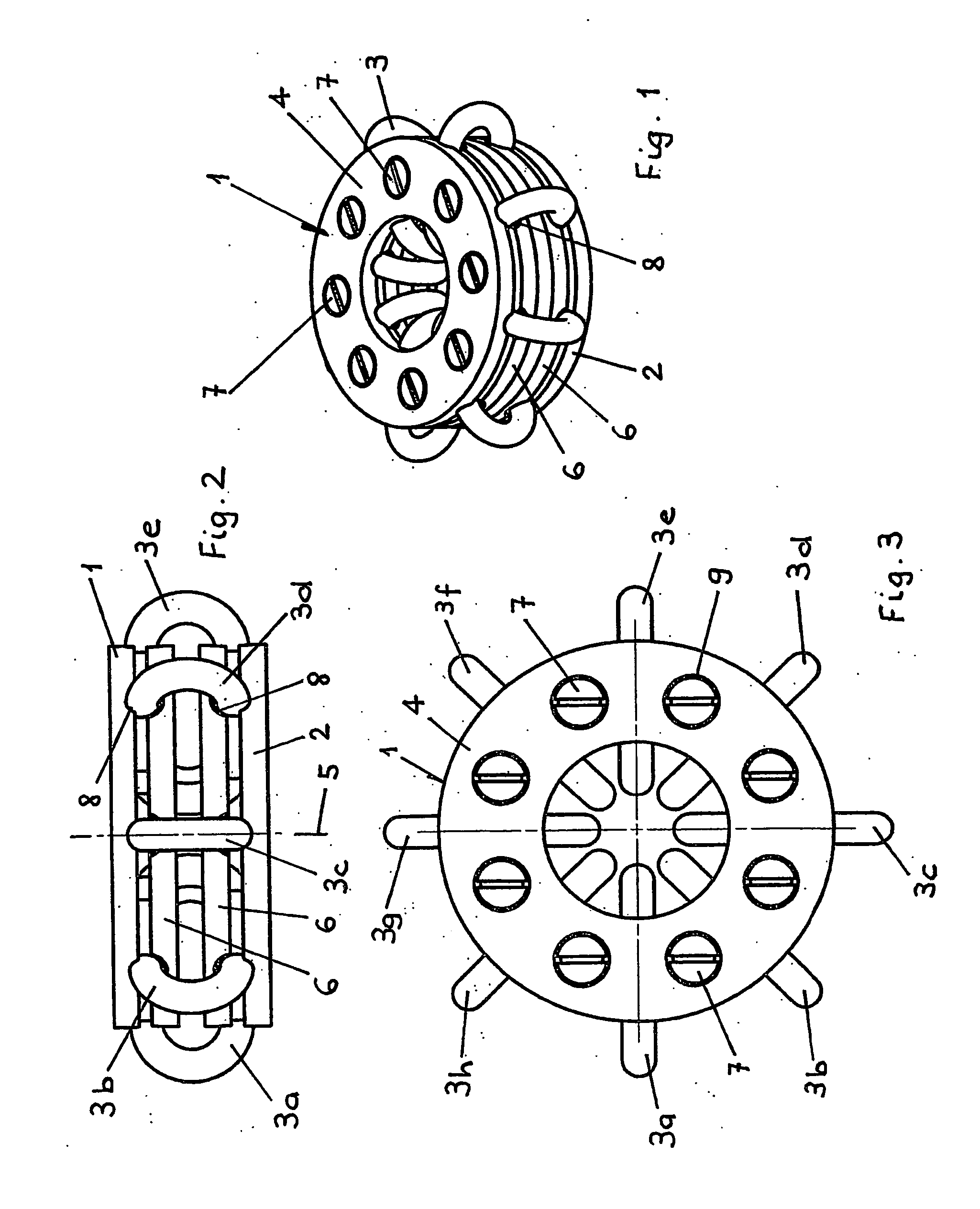
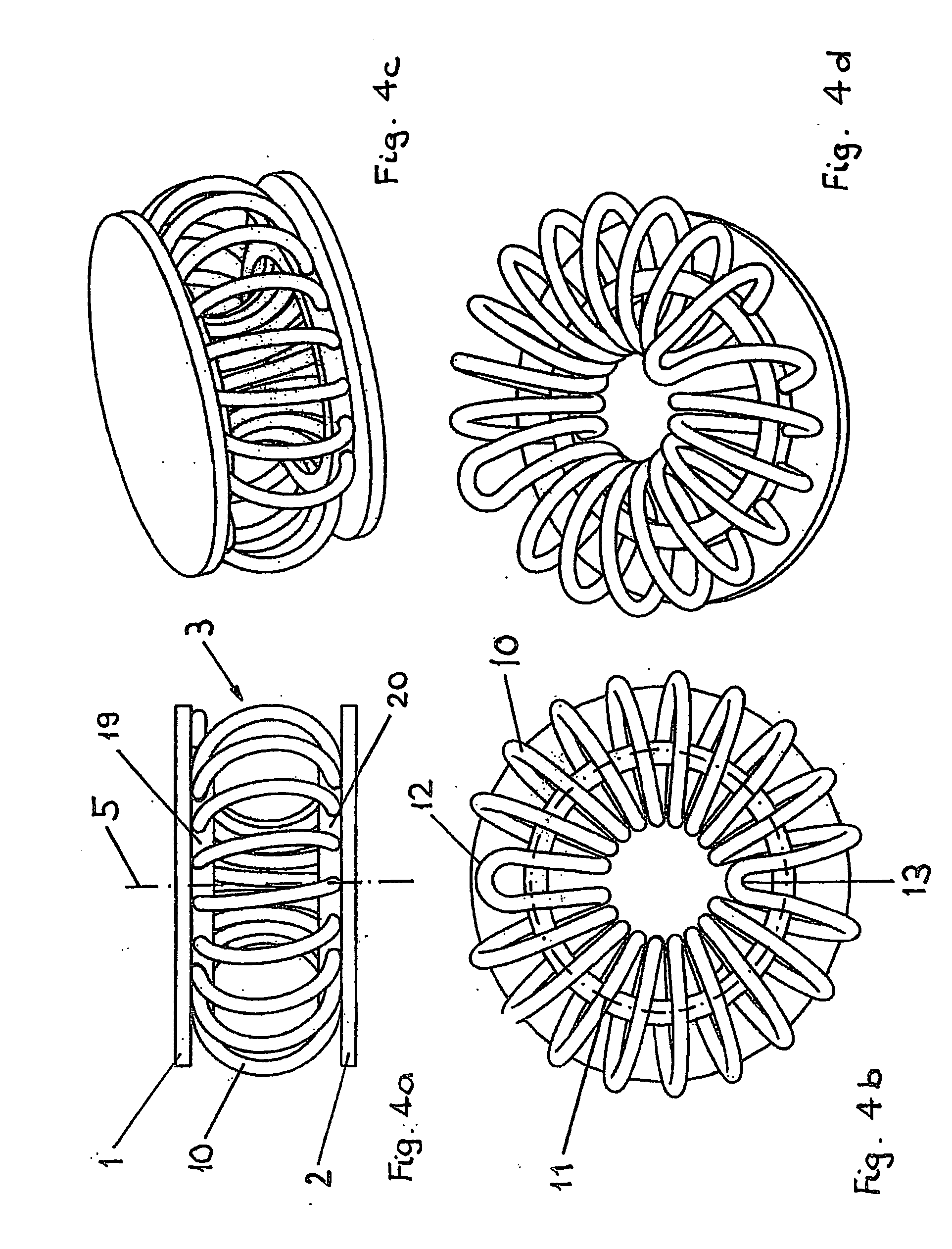
[0049] The intervertebral disc prosthesis shown in FIGS. 1 through 3 consists of an upper, circular apposition plate 1 suitable to come to rest against the base plate of a vertebra, further of a lower annular apposition plate 2 which is appropriate to come to rest against the cover plate of a vertebra, further two intermediate plates 6 which are configured between the two apposition plates 1, 2 and which are also circular, all plates being mounted perpendicularly to a common central axis 5.

[0050] A total of eight elastic devices 3 in the form of rings 3a-3h are configured between the two circular apposition plates 1, 2 and said devices run radially to the central axis 5, their annular plane being perpendicular to the apposition plates 1, 2.

[0051] In order that the intervertebral disc prosthesis be held together, the upper apposition plate 1 is connected to the adjacent intermediate plate by a total of eight screws 7 and in turn the lower apposition plate 2 is connected to its adja...


PUM

PropertyMeasurementUnit
Elasticityaaaaaaaaaa
Stiffnessaaaaaaaaaa
Perimeteraaaaaaaaaa

Abstract

Intervertebral disc prosthesis comprising an upper apposition plate appropriate to rest against the base plate of a vertebra, an apposition plate spaced apart from the apposition plate and suitable to rest against the upper plate of a vertebra, a plurality of elastic devices mounted between the two apposition plates and in their peripheral zones in a manner that the two apposition plates shall be displaceable in mutually resilient manner, and a central axis which runs essentially perpendicularly to the two apposition plates, the elastic devices being designed/configured in a manner that the intervertebral disc prosthesis as a whole exhibits asymmetrical stiffness.

Description

CROSS-REFERENCE TO RELATED APPLICATIONS [0001] This application is a continuation of International Application No. PCT / CH2003 / 00187, filed Mar. 24, 2003, the entirety of which is expressly incorporated by reference herein.FIELD OF THE INVENTION [0002] The present invention relates to a vertebral disc or intervertebral disc prosthesis, hereafter simply called intervertebral disc prosthesis. Such prostheses may be used as nucleus replacements, flexible cages or intervertebral disc prostheses, and are inserted posteriority (PLIF technique). When in the form of dynamic implants, they also may be emplaced between the dome extensions of adjacent vertebral discs. BACKGROUND OF THE INVENTION [0003] U.S. Pat. No. 5,458,642 (Beer) discloses an intervertebral disc prosthesis comprising an upper and a lower kidneys-shaped plate, these plates being each peripherally connected (about a central core) to each other by a plurality of helical springs. The helical springs are configured in equidistant...

Claims


Application Information

Patent Timeline
IPC IPC(8): A61F2/44A61F2/00A61F2/30
CPCA61F2/4425A61F2310/00796A61F2002/30113A61F2002/30125A61F2002/302A61F2002/30433A61F2002/305A61F2002/30518A61F2002/30565A61F2002/3057A61F2002/30604A61F2002/443A61F2002/444A61F2002/448A61F2220/0025A61F2220/0041A61F2230/0006A61F2230/0008A61F2230/0065A61F2250/0018A61F2002/30014A61F2002/30568
Inventor STUDER, ARMINTRACHSEL, JASONWYMANN, MARTIN
Owner SYNTHES USA
Why Eureka
Try Eureka