
Method and apparatus for firestopping a through-penetration

a technology of firestopping and through-penetration, applied in the field of firestopping, can solve the problems of omission of essential firestop materials, time-consuming and expensive installation, and inability to withstand repeated re-entry without the likelihood of material damage or damage, and achieves quick and easy installation, service or removal, and quick and easy installation.

Inactive Publication Date: 2006-03-16
3M INNOVATIVE PROPERTIES CO
View PDF7 Cites 58 Cited by
  • Summary
  • Abstract
  • Description
  • Claims
  • Application Information

AI Technical Summary

Benefits of technology

[0011] The central opening typically has a cross-sectional area that is at least as large as the cross-sectional area of the through-penetration opening. More particularly, the cross-sectional area of the central opening in the apparatus is typically large enough to accommodate any firestop material and any other components and still have an open area that is at least as large as the cross-sectional are of the through-penetration opening. In this manner, the entire cross-sectional area of the through-penetration opening can be used to pass items such as cables through the partition. In addition, because the apparatus is mounted adjacent the opening, it can be easily and quickly installed, serviced or removed.
[0012] The apparatus is also adjustable to allow items passing through the opening to be quickly and easily added or removed. Once installed, the device preferably remains in the place for the life of the opening. Thus, the device allows for the quick and easy installation or removal of items passing though the opening, but the device itself never needs to be removed or modified once it has been installed in the opening. The present invention finds particular application, for example, in the telecommunications industry where openings in walls, floors, and ceilings for cable passage are prevalent, and cables are frequently added to or removed from the opening.

Problems solved by technology

While such techniques are generally satisfactory for resisting the spread of fire and preventing the passage of smoke from one room or compartment of a structure to another, installation is time consuming and expensive.
In addition, firestops fabricated in this manner do not lend themselves to repeated re-entry without the likelihood of material damage or damage to the perimeter of the opening, do not remain in the opening during the cable work leading to potential omission of essential fire stop material upon re-closure, and do not lend themselves to ease of inspection without removal of at least a portion of the completed assembly.
In addition, removing cables from a typical through-penetration currently requires the existing intumescent material to be removed, discarded, and replaced completely or in part with new intumescent material.
This procedure is time consuming, expensive, and wasteful.
Because through-penetrations may be opened and closed numerous times during the service life of an opening to add or remove items from the opening, the costs associated with such systems can be significant.
Furthermore, such systems, installed in floor openings, require cover plates to meet fire and architectural demands.
Cover plates are typically made of 0.25 inch (6.4 millimeters) steel which makes them difficult to modify after initial fabrication and installation.
In addition, adjusting the contour of the cover to match the profile of the new cable bundle can be time consuming.
These prior devices and techniques, however, tend to suffer from one or more disadvantages, drawbacks or shortcomings.
For examples, these prior devices are mounted in the opening making installation difficult and occupying space in the opening that could otherwise be used to pass items from one room of the building to another.
Such a firestop device can provide considerable long-term cost saving to firestop users over currently available systems and techniques.

Method used


Image

  • Method and apparatus for firestopping a through-penetration
  • Method and apparatus for firestopping a through-penetration
  • Method and apparatus for firestopping a through-penetration

Examples


Embodiment Construction

[0023] For the purpose of this invention, the following terms are used herein:

[0024]“firestop material” refers to intumescent, endothermic, and ablative materials useful in resisting the spread of fire and smoke from one compartment of a structure to another. A firestop material may include an intumescent compound, an endothermic compound, or both an intumescent compound and an endothermic compound;

[0025]“intumescent material” refers to a material that expands to at least about 1.5 times its original volume upon heating to temperatures typically encountered in fire-like conditions.

[0026]“endothermic material” refers to a material that absorbs heat, typically by releasing water of hydration, by going through a phase change that absorbs heat (i.e. liquid to gas), or by other physical or chemical change where the reaction requires a net absorption of heat to take place.

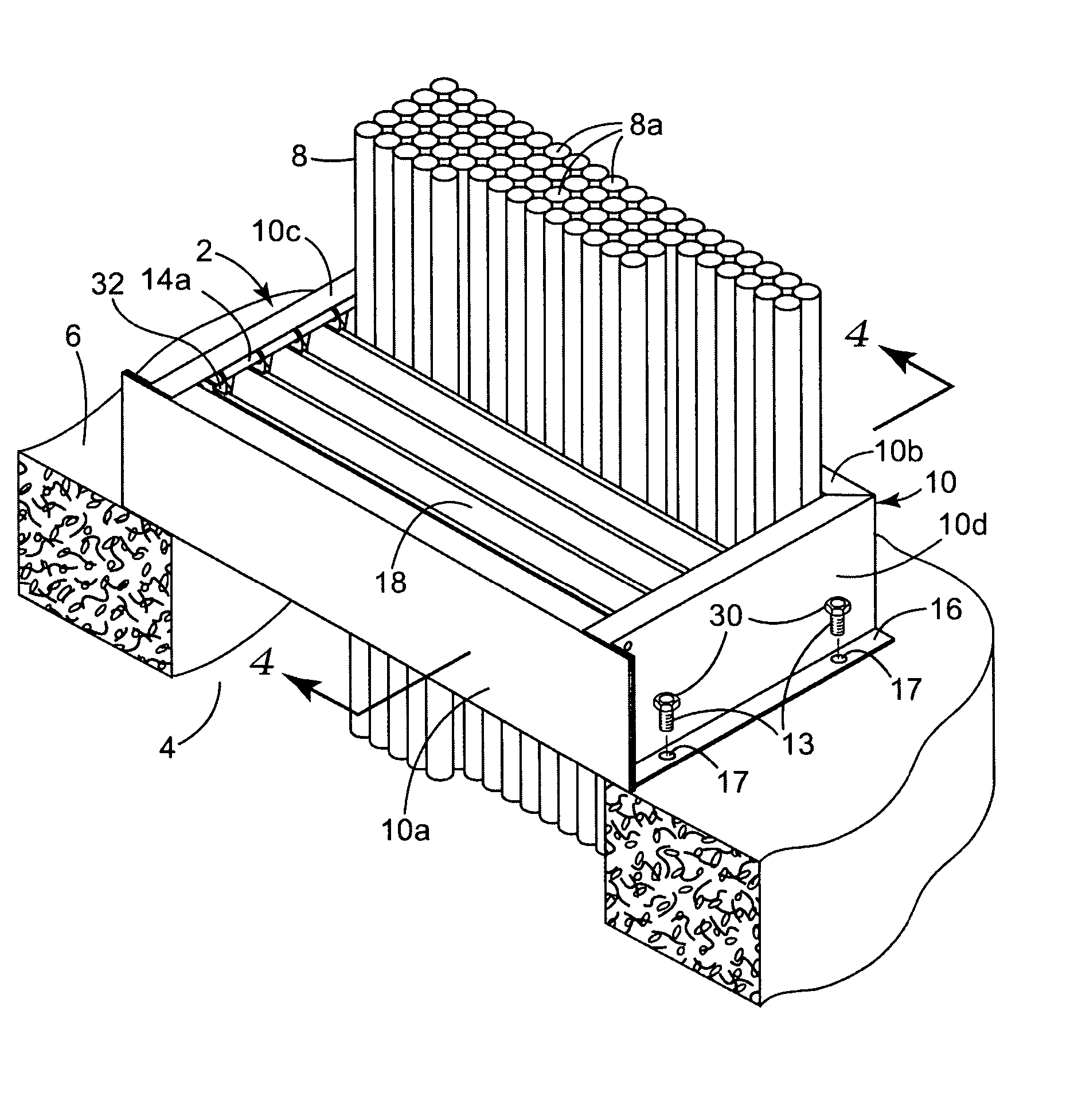
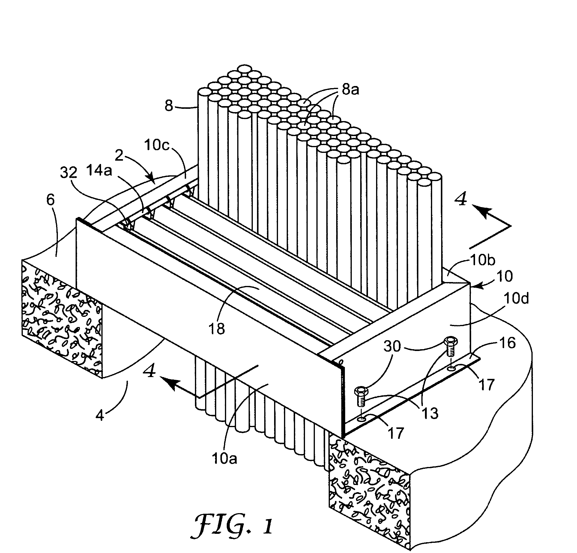
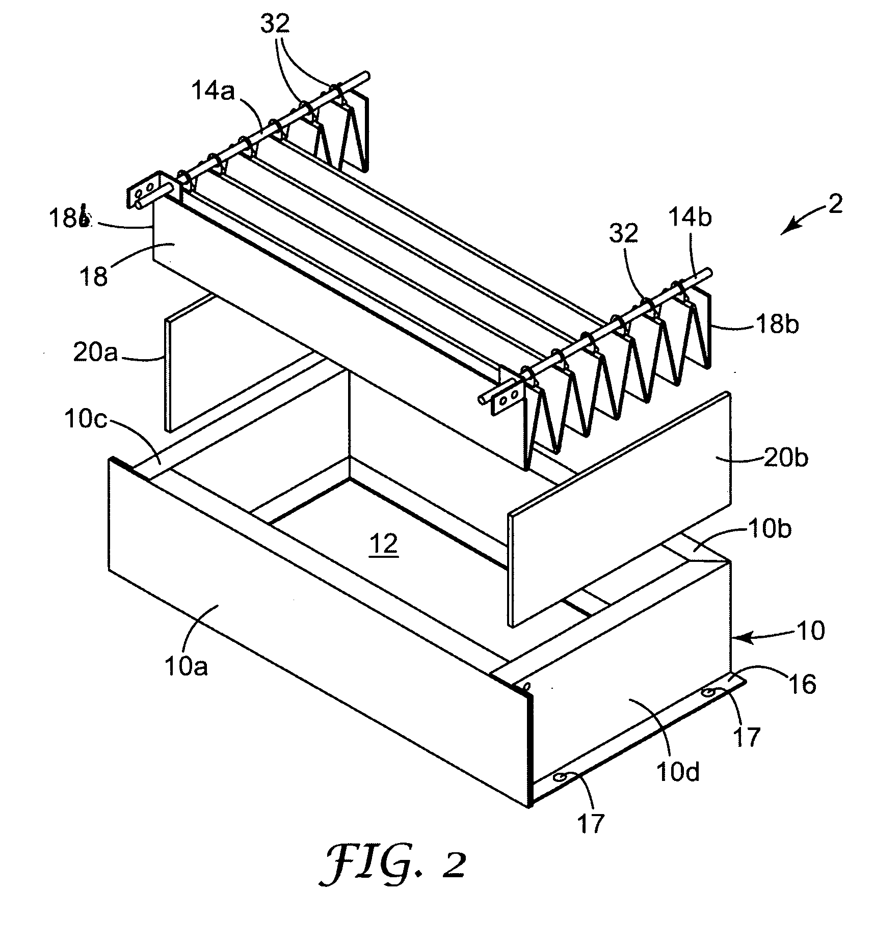
[0027] Referring now to the drawings, FIGS. 1-4 show a firestop device 2 arranged adjacent an opening or through-p...


PUM


Abstract

A method and apparatus for creating firestopping barrier in a partition, such as a wall, floor, or ceiling, that is mounted adjacent the opening includes a housing containing a central opening. The cross-sectional area of the housing is greater than the cross-sectional area of the through-penetration opening, and the housing is arranged external to the through-penetration opening with at least a portion thereof extending along a surface of the partition thereby to allow the housing to be installed adjacent the through-penetration opening. Firestop material is arranged within the housing.

Description

FIELD OF THE INVENTION [0001] The present invention relates generally to firestopping and, more particularly, to a method and apparatus for firestopping an opening in, for example, a wall, floor, or ceiling, which has items such as cables or wires passing through it. BACKGROUND OF THE INVENTION [0002] One way smoke and fire spreads from one part of a building to another is through passages or openings, often referred to as through-penetrations, in floors, walls, ceilings, or the like. Such openings are provided in the building to allow cables, wires, pipes or the like to pass from one area of the building to another. [0003] One technique currently used to prevent the spread of fire and passage of smoke through such openings uses intumescent sheets that are cut to follow the contour of the penetrating cables. A bead of moldable intumescent putty is then provided along the perimeter of the sheets. Other techniques utilize intumescent bricks or pillows. [0004] While such techniques are...

Claims


Application Information

Patent Timeline
Patent Type & Authority Applications(United States)
IPC IPC(8): E04C2/00
CPCH02G3/0412A62C3/16H02G3/22
Inventor MILLER, STEPHEN A.CORDTS, BRANDON L.
Owner 3M INNOVATIVE PROPERTIES CO
Learn More