Cold-formed steel joists

a cold-formed steel and joist technology, applied in the direction of joists, girders, buildings, etc., can solve the problems of limited span of conventional joists, increased labor and handling, etc., and achieve the effect of economic manufacturing

Inactive Publication Date: 2006-03-16
WATSON DENNISP +2
View PDF50 Cites 25 Cited by
  • Summary
  • Abstract
  • Description
  • Claims
  • Application Information

AI Technical Summary

Benefits of technology

[0006] An advantage of the present invention is a cold-formed joist that can span a distance of up to 100 feet, and is economically manufactured.
[0007] According to the present invention, the foregoing and other advantages are achieved in part by a joist having a first chord, the first chord having a length and a cross-section substantially symmetrical about a center line. The first chord cross-section comprises a horizontal base having two ends, and a pair of downwardly extending legs. Each leg comprises a chamfered portion extending downward and outward from one end of the base at an acute angle to the horizontal; an upper vertical portion, perpendicular to the base, extending downward from a lower end of the chamfered portion; an inwardly recessed portion, parallel to the base, extending towards the center line from a lower end of the upper vertical portion; and an attachment portion, perpendicular to the base, extending downward from an inner end of the inwardly recessed portion. The attachment portions of the legs define an opening for receiving a web of the joist, the opening extending substantially the entire length of the first chord.
[0008] Another aspect of the present invention is a seat member for attaching the joist to a structural member, the seat member having a pair of opposed vertical walls for fitting in the opening and abutting the chord attachment portions, a notch disposed such that the seat member is rigidly attachable to the attachment portions and to one of the web members, and a pair of flanges for attachment to the structural member.
[0009] A still further aspect of the present invention is method of assembling a joist, the method comprising providing an elongated joist chord with a cross-section having a center line and including a substantially horizontal base, a pair of substantially vertical side walls whose top ends are attached to the top wall, a pair of lower horizontal walls extending inward from the bottom ends of the side walls towards the center line of the chord cross-section, and a pair of vertical attachment portions extending downward from the inward-extending ends of the lower horizontal walls; rigidly assembling a web member having a pair of opposed walls spaced to fit between and abut the pair of attachment portions to the chord such that the attachment portions abut the web member opposed walls; and welding each of the web member walls to a respective one of the attachment portions without moving the web member / chord assembly, while the assembly is in a flat position.

Problems solved by technology

Disadvantageously, when mill run lengths are cut to match lengths required for particular applications, either a high rate of scrap results, or additional welded splices are made to the chords during fabrication, thereby increasing the required labor and handling.
Furthermore, the span of conventional joists is limited, requiring supporting structures, such as rafters, to be spaced closer than is desirable.

Method used


Image

  • Cold-formed steel joists
  • Cold-formed steel joists
  • Cold-formed steel joists

Examples


Embodiment Construction

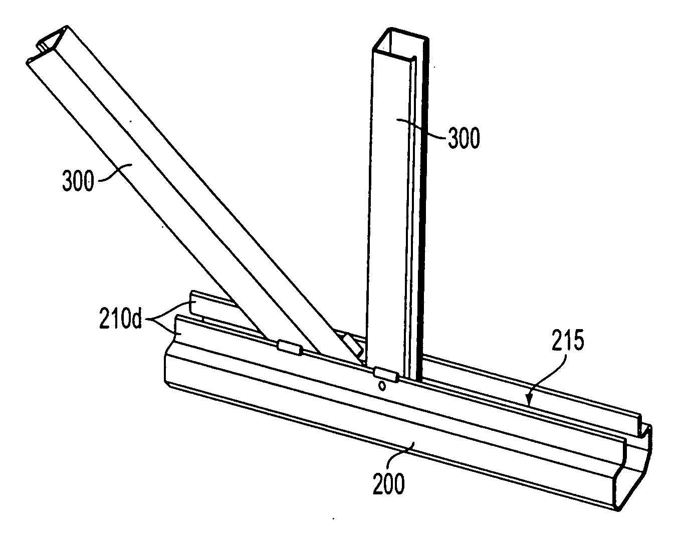
[0035] The joists of the present invention offer advantages over conventional open web bar joists because they are fabricated entirely of cold-formed steel components, made by running a coil of sheet steel through a series of rollers, each of which progressively bends the sheet to its final form. The use of cold-formed components provides manufacturing economies in reduced scrap and lower shop labor. It also provides field erection economies in a more rigid member to hoist to the roof during erection, easier field bolting to supporting framing, and easier installation of modem self-drilling fasteners than conventional open web steel bar joist.

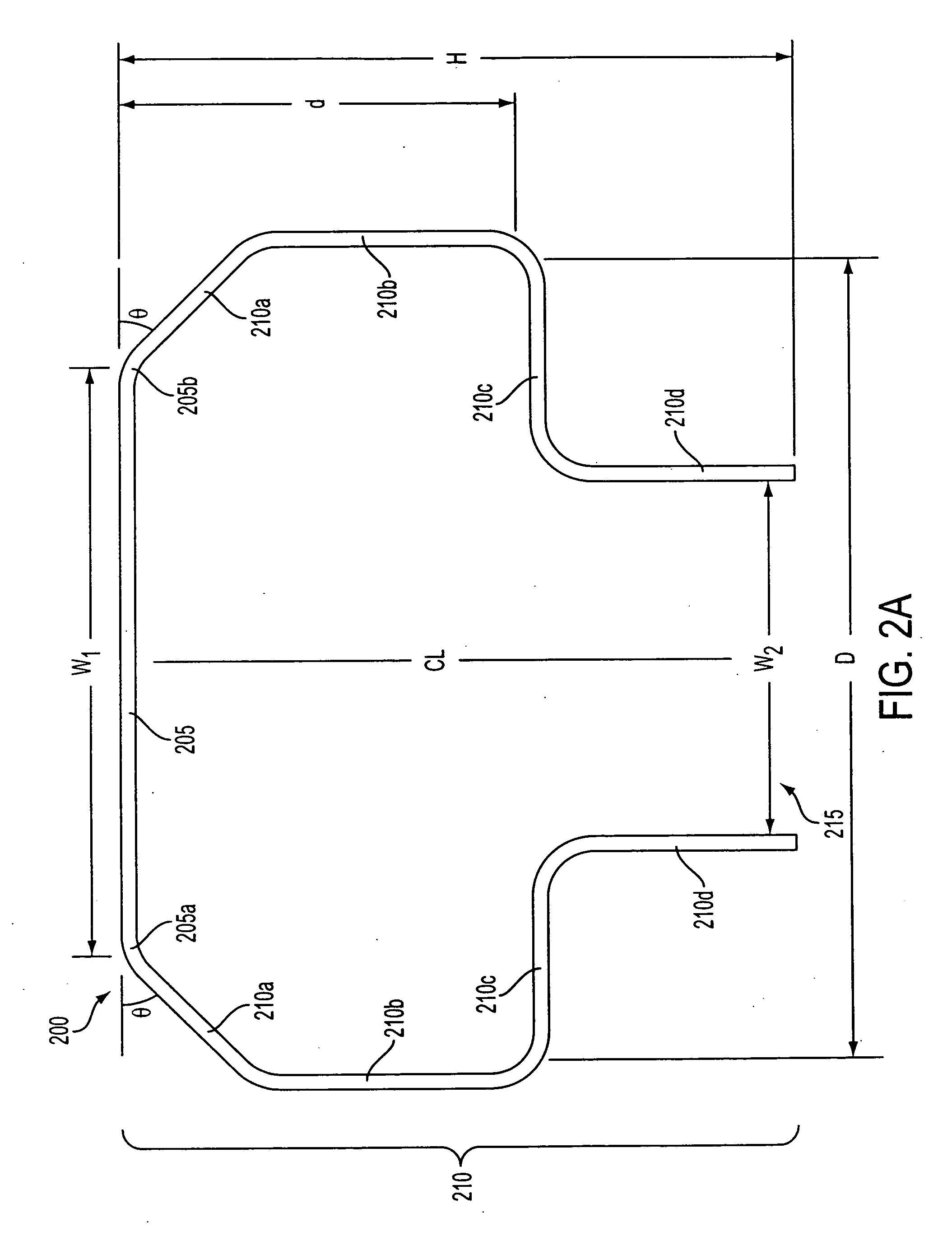
[0036] The open web cold-formed metallic joists of the present invention comprise cold-formed top and bottom chords and cold-formed metallic truss web members arranged in a vertical and diagonal fashion. The truss web members are shop welded to the chords. End connections, or “seats” are each shop welded to the top chord and to one of the webs...


PUM

PropertyMeasurementUnit
acute angleaaaaaaaaaa
angleaaaaaaaaaa
distanceaaaaaaaaaa

Abstract

A metallic joist is provided comprising cold-formed top and bottom chords, and cold-formed metallic truss web members arranged in a vertical and diagonal fashion shop welded to the chords. End connections, or “seats” are each shop welded to the top chord and to one of the webs. Each seat comprises a pair of vertical metallic planes that act as shear plates, welded to and extending outwardly and upwardly of the end portion of the top chord of the joist, and portions extending horizontally either side of the chord and punched with holes for easy field bolting to beams or other supporting elements. Each of the chords comprises a planar base and a pair of legs. Each leg comprises a chamfered portion extending downward and outward from one edge of the base at an acute angle to the horizontal; e.g., about 45 degrees, for stiffening the longitudinal edges of the base, to accommodate axial and moment forces. An upper vertical portion, perpendicular to the base, extends downward from a lower end of the chamfered portion to provide a planar width of material to accommodate axial and moment forces. An inwardly recessed portion parallel to the base extends towards the chord's center line from a lower end of the upper vertical portion; and an attachment portion, perpendicular to the base, extends downward from an inner end of the inwardly recessed portion. The inventive chord imparts the joist of the present invention with enough strength and stiffness to span up to 100-foot lengths.

Description

FIELD OF THE INVENTION [0001] The present invention relates to lightweight frame construction for residential and commercial buildings. The present invention has particular applicability to the manufacture of lightweight open web truss girders used in roof and floor applications in building construction. BACKGROUND ART [0002] Roof and floor structures employing lightweight prefabricated steel trusses are commonly used in low-rise buildings with all types of end uses, including residential and commercial uses. Structures made from steel trusses are well suited for the support of uniformly distributed roof or floor loads, suspended ceilings, ducts, sprinklers and lights. As a roof or floor joist, typical lightweight steel structural members are adapted to be secured to wall constructions of a variety of building systems, including masonry, concrete, wood, steel or other supporting members. [0003] Fabrication and use of steel trusses, such as open web joists, for construction dates fro...

Claims


Application Information

Patent Timeline
Patent Type & Authority Applications(United States)
IPC IPC(8): E04C3/02C22CE04B7/08E04C3/04E04C3/09
CPCE04C3/09E04C2003/0491E04C2003/0486E04C2003/0473
Inventor WATSON, DENNISPGOLOVIN, MAURYTONEY, PATRICK
Owner WATSON DENNISP
Why Eureka
Try Eureka