Actuator device

a technology of actuator and cover, which is applied in the direction of anti-theft devices, toothed gearings, gearings, etc., can solve the problems of gear rotating by an excessive angle, deformation or increased cost, etc., and achieve the effect of preventing deformation and breakage of the cover

Inactive Publication Date: 2006-03-16
MITSUBA CORP
View PDF7 Cites 6 Cited by
  • Summary
  • Abstract
  • Description
  • Claims
  • Application Information

AI Technical Summary

Benefits of technology

[0008] The invention is accomplished in order to solve the problems. An object of the invention is to provide a low-cost actuator device capable of reliably preventing deformation and breakage of the cover and reliably rotating the output gear within a predetermined angle and stopping the same on any occasion.

Problems solved by technology

In the related art steering lock device, when the projection of the output gear is brought into contact with and locked to the projection of the cover, a heavy load is applied to the projection of the cover to let the cover float, which is likely to cause deformation or breakage of the cover.
Deformation of the cover could fail to limit the rotation angle of the output gear thus causing the gear to rotate by an excessive angle.
The elastic element on the projection of the cover adds to the number of parts, which leads to an increased cost.

Method used


Image

  • Actuator device
  • Actuator device
  • Actuator device

Examples


embodiment 1

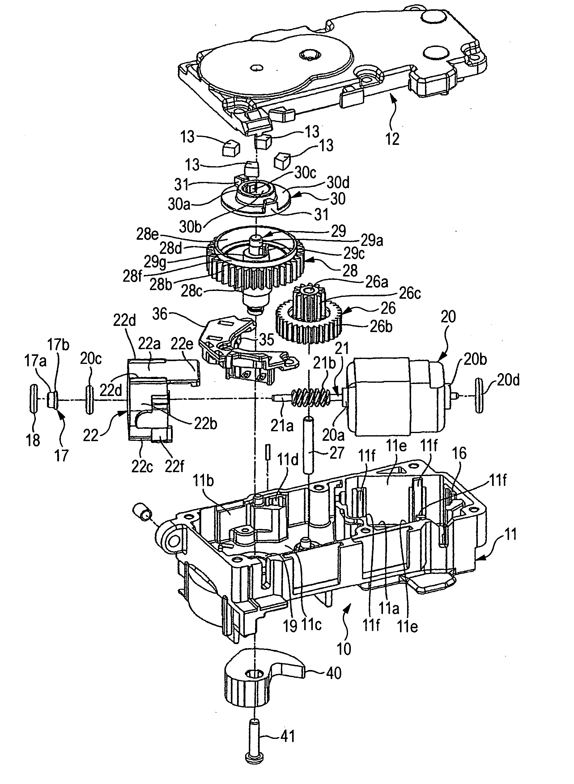
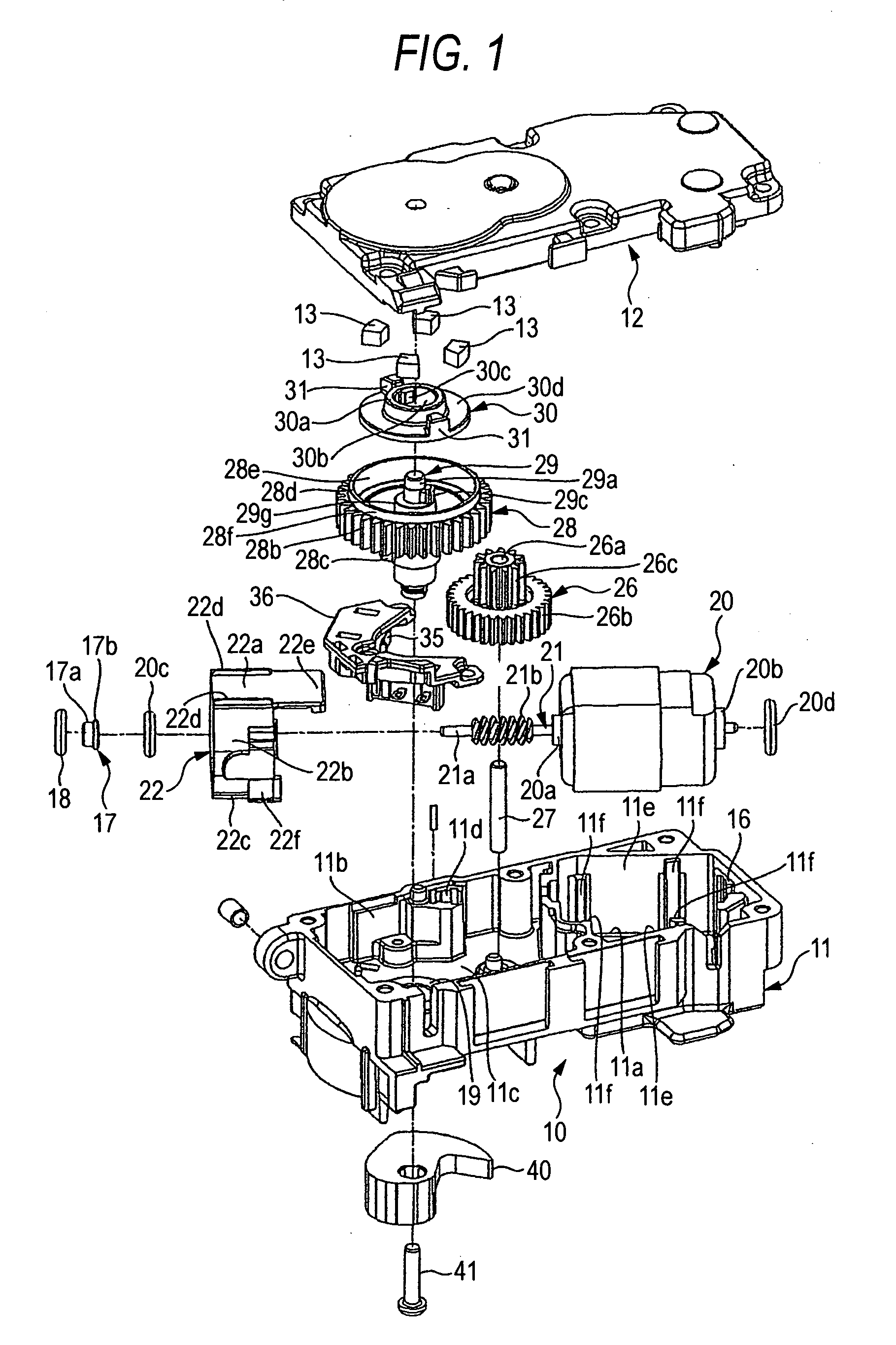
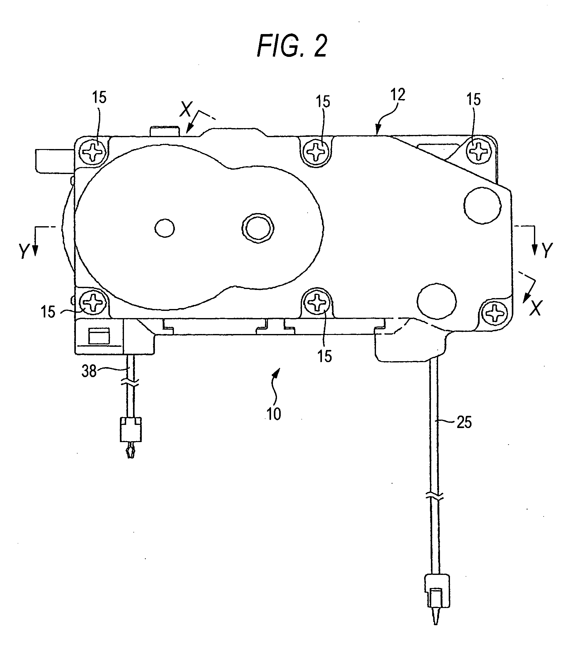
[0065]FIG. 1 is an exploded perspective view of a steering lock device according to Embodiment 1 of the invention. FIG. 2 is a plan view of the steering lock device. FIG. 3 is a bottom view of the steering lock device. FIG. 4 is a perspective view of the steering lock device seen from the bottom. FIG. 5 is a rear view of the steering lock device. FIG. 6 is a plan view of the inside of the case of the steering lock device. FIG. 7 is a cross section cross section taken along line X-X of FIG. 2. FIG. 8 is a side view of a motor used in the steering lock device. FIG. 9 is a plan view of the motor. FIG. 10A is a rear view of a cylindrical elastic member attached to the motor. FIG. 10B is a side view of the elastic member. FIG. 10C is a plan view of the elastic member. FIG. 11A is an enlarged cross section showing the terminal connecting part of the motor. FIG. 11B is an enlarged cross section showing a state where a terminal is connected to the terminal connecting part. FIG. 11C is a par...


PUM


Abstract

The actuator device includes: a motor housed in a case having a cover; an output gear driven to rotate by the drive shaft of via a deceleration gear; an output shaft rotatably supported by the case and rotating together with the output gear; and an output cam mounted on the output shaft; the actuator device having a receiving recessed part accommodating a stopper element on the top surface of the output gear, a stopper element rotatably mounted on the output shaft facing inside the receiving recessed part, and a locking projection part that is locked to and separated from the projection part of the output shaft and a stopper on the stopper element; and stopper where each stopper of the stopper element is locked to the inner surface of the cover to limit the rotation angle of the output gear.

Description

BACKGROUND OF THE INVENTION [0001] The present application claims foreign priority based on Japanese Patent Application No. 2004-247001 filed on Aug. 26, 2004, the content of which is incorporated herein by reference in its entirety, and concurrently with the filing of this patent application. [0002] The present invention relates to an actuator device preferably used for example in a steering lock device for locking / unlocking the steering shaft of a vehicle. [0003] A steering lock device as a related art actuator device includes: a case having a cover that covers a motor housing unit and a gear housing unit; a motor housed in the motor housing unit of the case; an output gear rotatably housed in the gear housing unit of the case, the output gear driven to rotate via a deceleration gear by the driving shaft of the motor; an output shaft penetrated by and fixed to the shaft of the output gear and rotating together with the output gear; an output cam mounted on the output shaft for loc...

Claims


Application Information

Patent Timeline
Patent Type & Authority Applications(United States)
IPC IPC(8): F16H1/16B60R25/02B60R25/0215
CPCB60R25/02153Y10T74/19828B60R25/02156
Inventor KAWAMURA, YUJINAKAMURA, IKUOKAWAMOTO, MAKITO
Owner MITSUBA CORP
Why Eureka
Try Eureka