Elevator entrance sill structure and installation method

a technology for elevators and sills, applied in elevators, transportation and packaging, parkings, etc., can solve the problems of reducing the time frame associated and elevator contractors cannot keep up with the pace of building, so as to facilitate the work of other trades, facilitate the expansion of the range of motion, and facilitate the effect of adding

Inactive Publication Date: 2006-03-16
FRIEDMAN HAROLD S
View PDF11 Cites 33 Cited by
  • Summary
  • Abstract
  • Description
  • Claims
  • Application Information

AI Technical Summary

Benefits of technology

[0035] Elevator entrances must be aligned very carefully to the rails and no part of the entrance is more critical than the sill. The elevator door sill assembly of the present invention provides structures with a variety of slots and hardware to allow the sill to be adjusted in all planes with a very wide range of motion. Extension brackets can also be easily added to expand the range of motion without adverse effect on the structural strength. This elevator sill assembly and installation method incorporates a design feature to facilitate the work of other trades as they relate to the entrance. Slots punched

Problems solved by technology

While advances in building construction methodology and hi-tech products have dramatically decreased the time frame associated with erecting today's High-rise structures

Method used


Image

  • Elevator entrance sill structure and installation method
  • Elevator entrance sill structure and installation method
  • Elevator entrance sill structure and installation method

Examples


Embodiment Construction

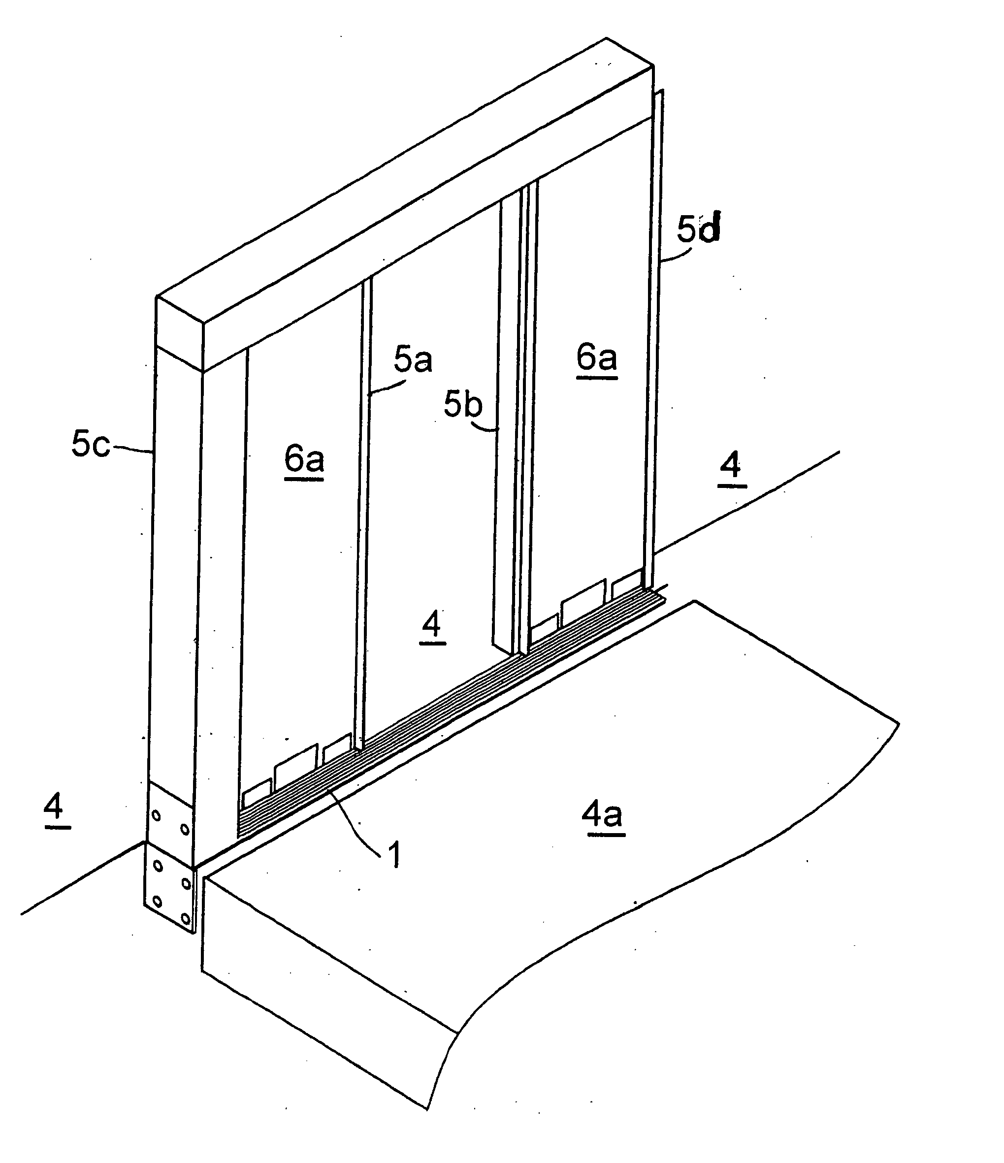
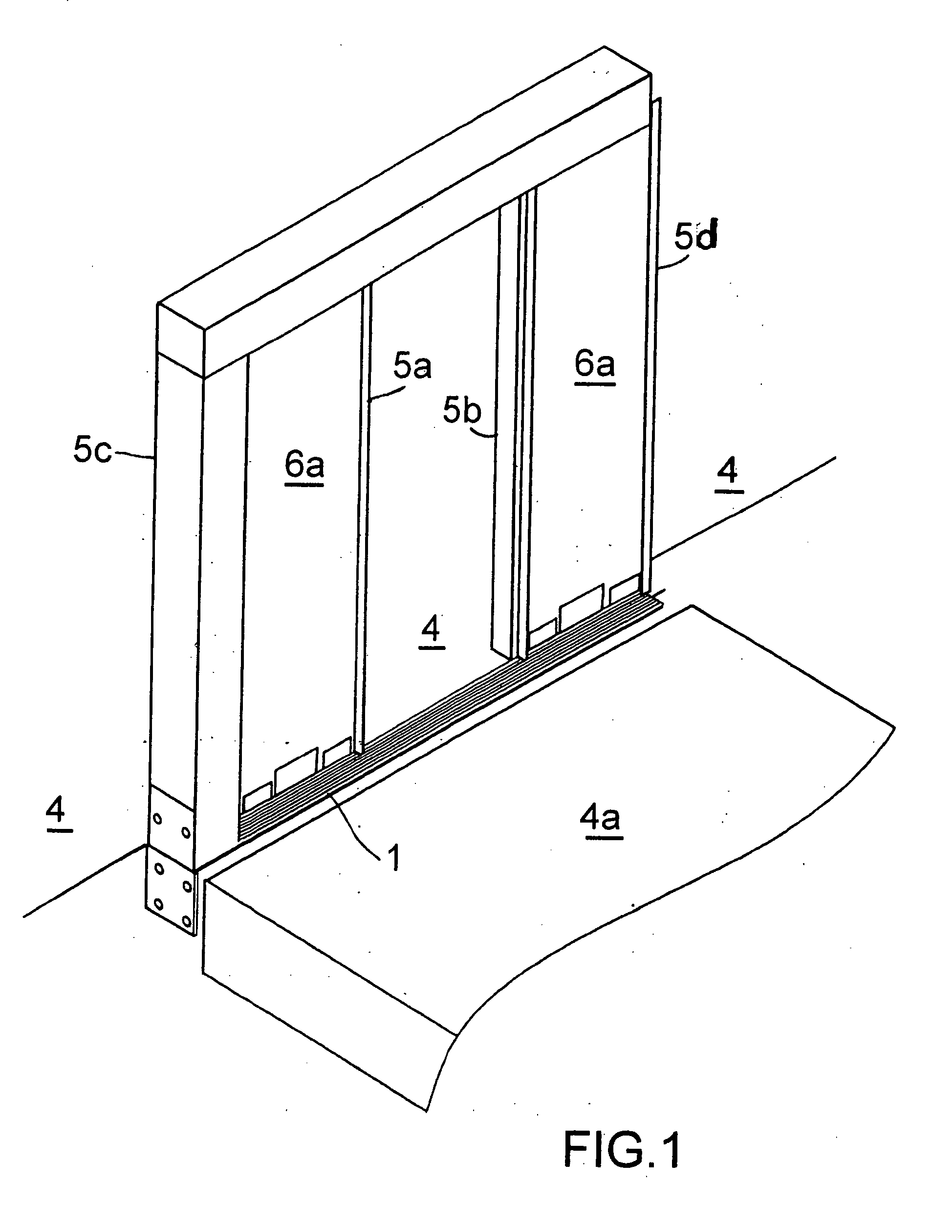
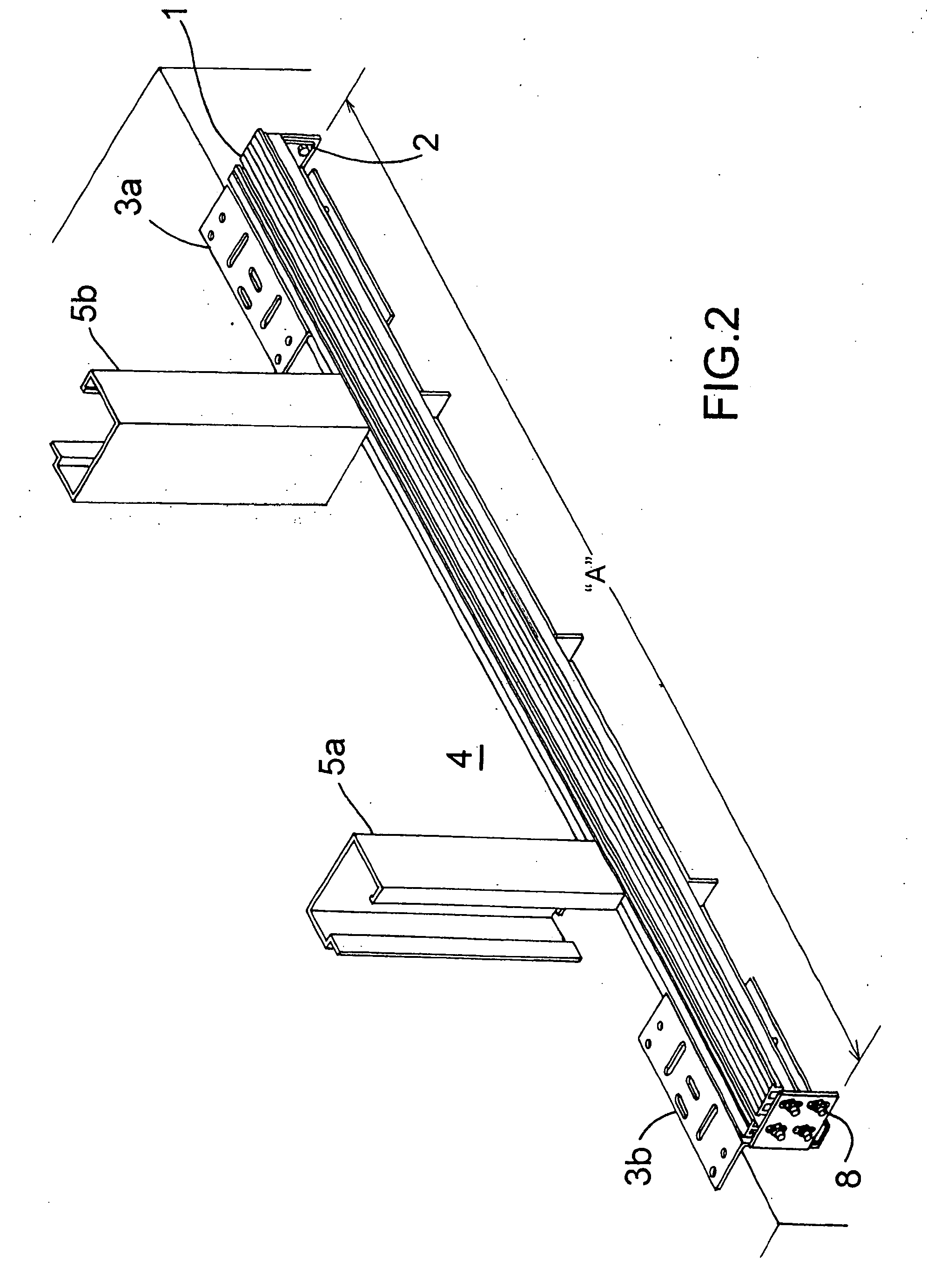
[0110] The elevator door entrance sill assembly of the present invention is attached to the building hall floor 4 forming the elevator door opening. As illustrated in FIGS. 1, 2 and 3, the sill assembly includes a sill 1 mounted on a support cradle 2. The sill is for a sliding elevator door that rides in a track in the sill. At opposite ends, the cradle 2 is supported and attached to the building floor by shaped end adjustable support brackets 3a and 3b which provide shoe like support for the cradle 2. The adjustable support brackets 3a and 3b are mounted on the building floor 4 at either side of the elevator vertical door frames 5a and 5b. Outer vertical supports 5c and 5d form the structure for the elevator entrance as shown in FIG. 1. The sliding elevator doors 6 are in an open position to provide access from the elevator floor area 4a to the building hall floor 4.

[0111] As illustrated in FIGS. 2, 3 and 4, the sill cradle 2 is bolted at opposite ends to the brackets 3a and 3b by...


PUM


Abstract

The invention relates to a highly advantageous, novel and cost saving way of solving a difficult and expensive problem in the structure and installation and leveling of an elevator sill. The assembly structure and installation is one of simplicity and ease of installing from the hallway. The elevator door sill assembly is installable from a hallway without the use of a moving elevator platform. An elevator door sill is provided for mounting at the elevator entrance adjacent to the elevator shaft. The sill is mounted to a support assembly which provides the necessary stiffness to prevent the sill from flexing. Hinge supports are attached to the sill assembly and mounted on the building floor adjacent to the elevator shaft and rotatable to extend upwardly from the floor and out of the elevator shaft. The door sill assembly is attachable to the hinge support while in the upward or vertical position out of the elevator shaft. The hinge support and the sill assembly are rotatable downwardly to a horizontal position on the floor after attachment of the sill assembly to the hinge support with the sill assembly extending into the elevator shaft.

Description

[0001] This application is a Continuation-in-Part of pending application Ser. No. 10 / 233,277.FIELD OF INVENTION [0002] The present invention relates to building construction and more particularly to an advantageous elevator entrance sill structure and installation method that allows for complete installation from the hallway without the use of a moving elevator platform. BACKGROUND OF INVENTION [0003] A number of structures and methods are known and commonly used to install an Elevator Entrance Sill including the following: [0004]“Sill Support Pocket”. This method is typically used in a building where the structural method of support is poured concrete. The concrete hall floor slab extends into the shaft and a pocket approximately 2″ to 3″ deep must be created in the top edge of the slab inside the elevator shaft in the opening where the entrance is to be located. Making a pocket is a time consuming and costly procedure. The sill is fastened to this pocket by means of adjustable bra...

Claims


Application Information

Patent Timeline
IPC IPC(8): B66F7/06
CPCB66B13/301
Inventor FRIEDMAN, HAROLD S.FREIDMAN, JEFFREYGUSLAWSKI, WALTERKARAZIM, GEORGE
Owner FRIEDMAN HAROLD S
Why Eureka
Try Eureka