Adaptive biasing concept for current mode voltage regulators

a voltage regulator and current mode technology, applied in the direction of electrical variable regulation, process and machine control, instruments, etc., can solve the problems of large voltage transients, conventional ldo regulators are very problematic in the transient response area, and the timing glitch of the ldo output voltage, so as to stabilize the biasing current

Active Publication Date: 2006-03-16
DIALOG SEMICONDUCTOR GMBH
View PDF10 Cites 41 Cited by
  • Summary
  • Abstract
  • Description
  • Claims
  • Application Information

AI Technical Summary

Benefits of technology

[0016] In accordance with the objects of this invention a circuit for a current mode voltage regulator having dynamic biasing for the complete loop transfer function has been achieved. Said circuit is comprising, firstly, an operational transconductance amplifier (OTA), wherein its effective transconductance gm is linearly dependent upon its biasing current, having inputs and an output, wherein its output is connected to a means of constant current amplification and the inputs are a reference voltage, a feedback voltage from a voltage divider, wherein said biasing current, which is generated by amplification of the output current of said OTA using a constant current amplification factor is forming a feed forward loop. Secondly, the circuit invented comprises said means of constant current amplification having an input and two outputs, wherein its input is said output current of said OTA and a first output is said biasing current of said OTA and a second output is the output current of said voltage regulator. Furthermore the circuit comprises a low-pass filter stabilizing said biasing current, and said voltage divider providing a voltage being linearly correlated to the output voltage of said voltage regulator and wherein said voltage provided by the voltage divider is used as an input of said OTA forming a negative feedback loop by connecting the regulator output to the OTA input.
[0017] In accordance with the objects of this invention a circuit to for a current mode voltage regulator having dynamic biasing for the complete loop transfer function has been achieved. The circuit invented comprises, firstly, an OTA from a Mirror-Transconductor Amplifier type, wherein its effective transconductance gm is linearly dependent upon its biasing current, having inputs and an output, comprising a differential amplifier and a first current mirror configuration, wherein the output of the OTA is connected to a second current mirror configuration for current amplification and a first input of said differential amplifier is a reference voltage and a second input of said differential amplifier is a feedback voltage from a voltage divider, and said current biasing said differential amplifier is generated by amplification of the output current of the OTA using a constant current amplification factor, wherein said biasing current forms a feed forward loop. Secondly, the circuit invented comprises said second current mirror configuration for current amplification having an input and two outputs, wherein its input is said output current of said OTA and a first output is said biasing current of said OTA and a second output is the output current of said voltage regulator. Thirdly, the circuit comprises a gmc-filter type low-pass filter stabilizing said biasing current comprising a current mirror and a capacitor wherein said current mirror is amplifying said biasing current. Furthermore the circuit comprises said voltage divider providing a voltage being linearly correlated to the output voltage of said voltage regulator, which is connected to the second input of said differential amplifier forming a negative feedback loop by connecting the regulator output to the OTA input.
[0018] In accordance with the objects of this invention a method for a current mode voltage regulator to achieve dynamic biasing for the complete loop transfer function has been reached. The method invented comprises, firstly, the provision of a current mode voltage regulator comprising an operational amplifier (OTA) having a transconductance, which is linearly dependent on its biasing current, a low-pass filter, a voltage divider, and a current amplifier. The next steps of the method are to feed a voltage representing the output voltage of said regulator back to said OTA, to use said voltage of the previous step to control the output current of said OTA, and to amplify said output current of said OTA using a constant current amplification factor to generate a biasing current of said OTA; stabilize said biasing current of said OTA; and amplify said output current of said OTA using a constant current amplification factor to generate the output current of the regulator.

Problems solved by technology

This quick change of load results in a temporary glitch of the LDO output voltage.
Most digital circuits do not react favorably to large voltage transients.
Conventional LDO regulators are very problematic in the area of transient response.
Conventional means to compensate frequency dependencies are limiting the load regulation performance and the accuracy of the output.
Linear voltage regulators (LDO's) have either a fixed biasing current, which results in poor efficiency for small load currents, or they have a (nonlinear) dynamic biasing current, which changes the internal operating point when the load varies.
This negatively affects stability and requires a large silicon area for compensation.
Further the LDO suffers in one or the other way because of these variations.

Method used


Image

  • Adaptive biasing concept for current mode voltage regulators
  • Adaptive biasing concept for current mode voltage regulators
  • Adaptive biasing concept for current mode voltage regulators

Examples


Embodiment Construction

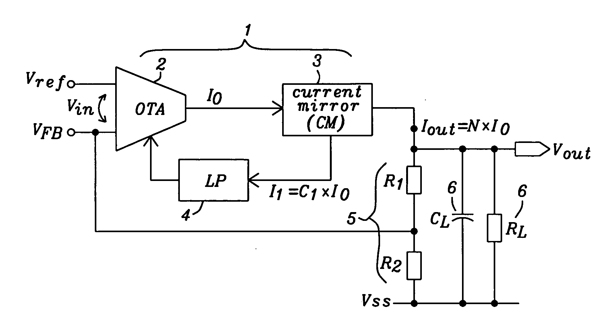
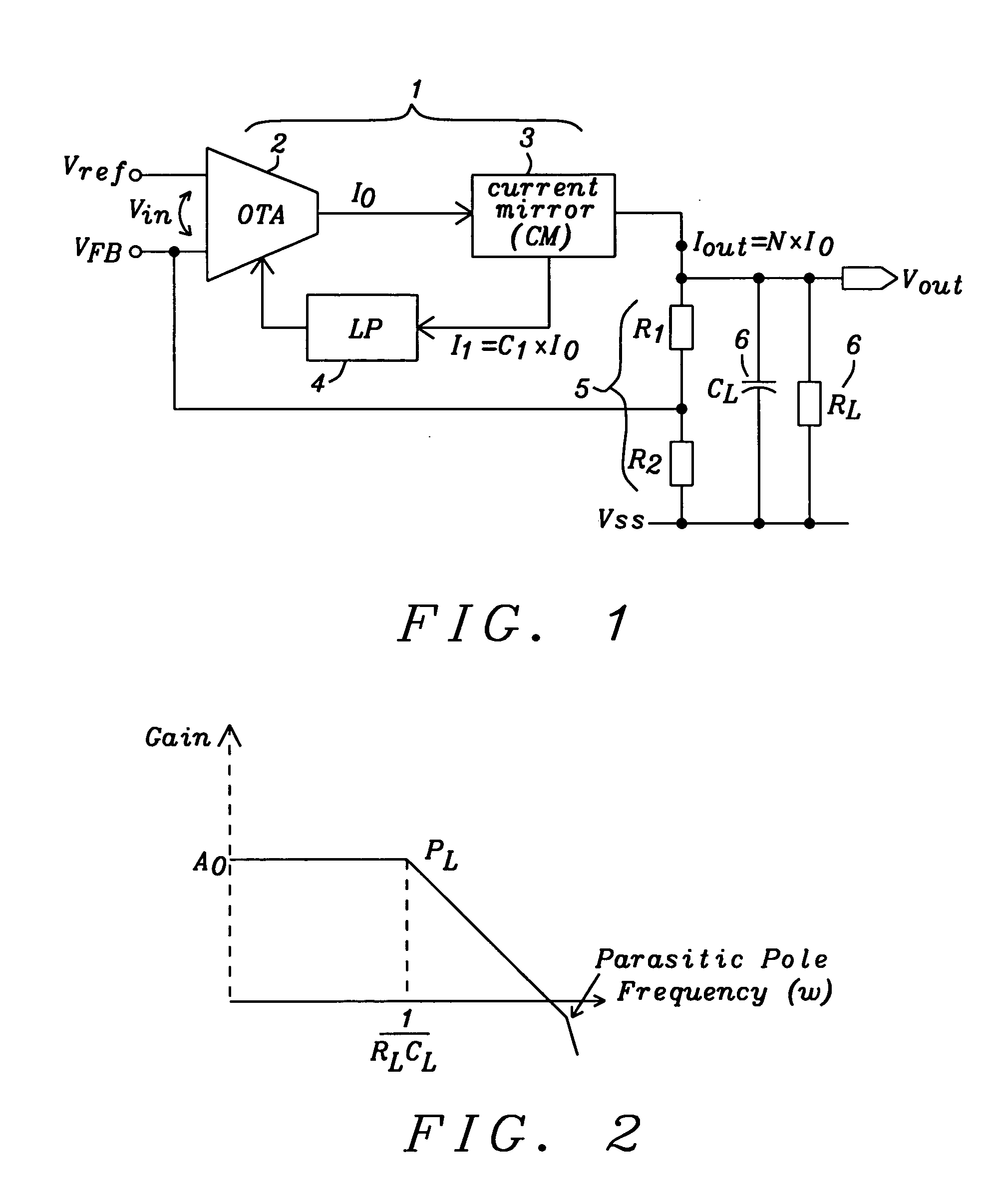
[0024] The preferred embodiments of the present invention disclose novel circuits and methods for current mode LDO voltage regulators achieving a constant and high efficiency of higher than 99.5% without requiring a large “Miller compensation” capacitor to stabilize the regulator feedback loop under all operating conditions.

[0025] Key point of the invention is that the complete LDO is dynamically biased depending on the output load in a strictly linear way. The new structure has a transfer function, which is highly predictable since it depends mainly on external components and physical constants and not on process variations. Especially the constant DC-loop gain is a key factor. It allows a simple frequency compensation determined only by the external load outside the chip. As a result the stability condition (phase margin) remains constant over the complete operating range.

[0026]FIG. 1 shows a principal block diagram of the present invention showing an adaptive biasing concept fo...


PUM


Abstract

Circuits and methods to achieve dynamic biasing for the complete loop transfer function of a current mode voltage regulator have been achieved. The circuit comprises a Mirror-Transconductor Amplifier type operational transconductance amplifier (OTA) wherein its transconductance is linearly dependent on its biasing current. This biasing current is a linearly derivative of the OTA's output current. A current amplification circuit couples the regulator output current linearly with said OTA's output current. In this configuration the iterative biasing of the OTA forms a feed-forward loop, which contains a low-pass filter for stability and a negative feedback loop is closed by connecting the regulator voltage output to the OTA input. The invention realizes a purely current mode regulator since all internal currents are generated as a fraction of the output load.

Description

BACKGROUND OF THE INVENTION [0001] (1) Field of the Invention [0002] This invention relates generally to voltage regulators, and more particularly to a current mode low dropout (LDO) voltage regulator having a linear adaptive biasing current technique. [0003] (2) Description of the Prior Art [0004] Low-dropout (LDO) linear regulators are commonly used to provide power to low-voltage digital circuits, where point-of-load regulation is important. In these applications, it is common for the digital circuit to have different modes of operation. As the digital circuit switches from one mode of operation to another, the load demand on the LDO can change quickly. This quick change of load results in a temporary glitch of the LDO output voltage. Most digital circuits do not react favorably to large voltage transients. An important goal for voltage regulators is to isolate sensitive circuitry from the transient voltage changes of the battery. [0005] Conventional LDO regulators are very probl...

Claims


Application Information

Patent Timeline
Patent Type & Authority Applications(United States)
IPC IPC(8): G05F1/56G05F1/563G05F1/575
CPCG05F1/575
Inventor EBERLEIN, MATTHIAS
Owner DIALOG SEMICONDUCTOR GMBH
Why Eureka
Try Eureka