

Ink jet recording method, recording apparatus, and recorded object
- Summary
- Abstract
- Description
- Claims
- Application Information
AI Technical Summary
Benefits of technology
Problems solved by technology
Method used
Image

Examples
Embodiment Construction
[0065] Hereinafter, preferred embodiments of the present invention will be explained in detail by way of example, with reference to the accompanying drawings. It is not intended that relative positions of constitutional elements, formulas, numerical values, and the like, as described in this embodiment will not limit the scope of the present invention, unless otherwise specified.
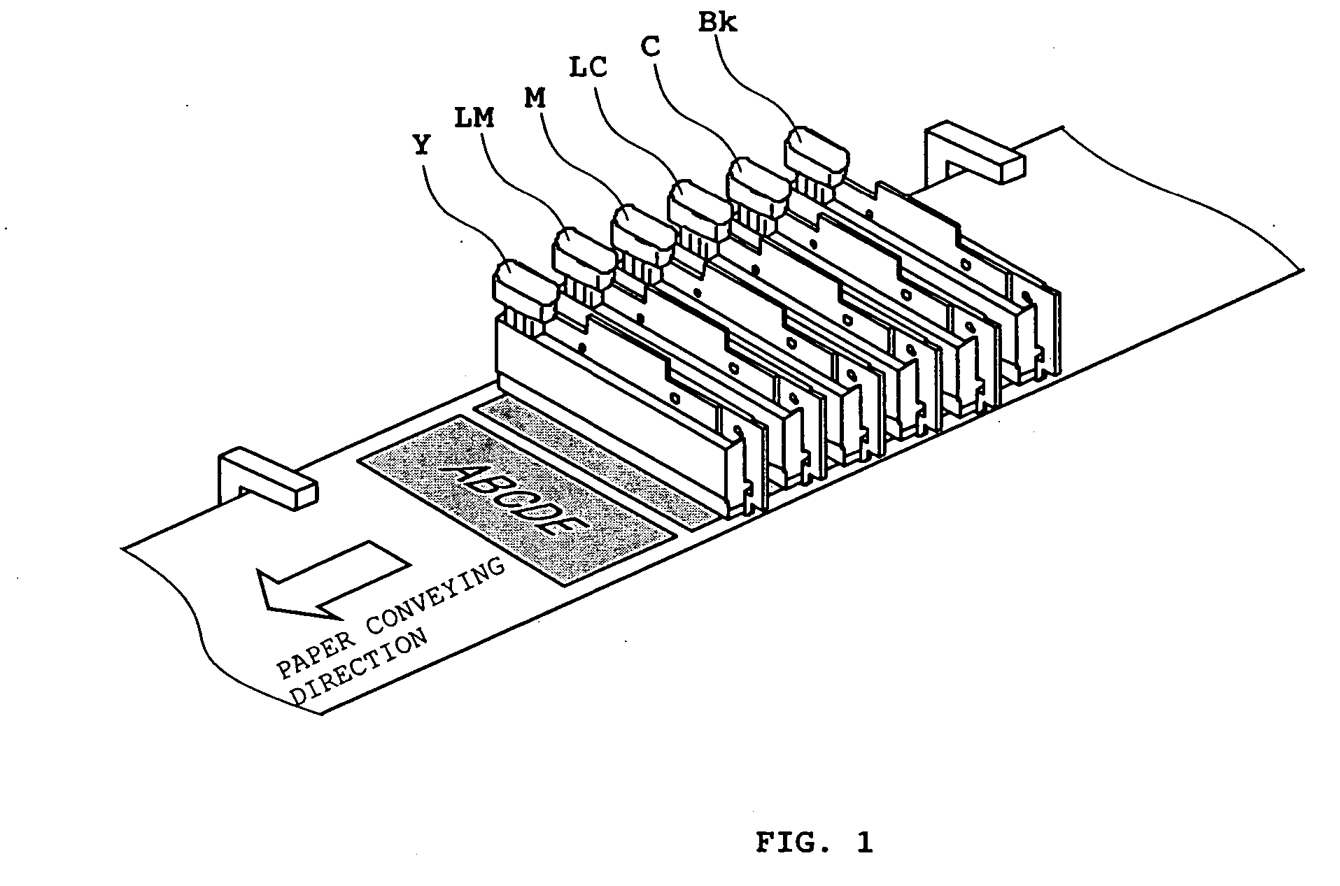
[0066]FIG. 1 is a perspective view to schematically explain an array of ink jet recording heads according to a preferred embodiment of the present invention.
[0067] The recording head as a recording means in the preferred embodiment are formed by arranging a plurality of line heads of long-length type in parallel, each linearly placing a plurality of recording elements, being orthogonal to a direction into which a paper sheet is conveyed. In the example as shown in FIG. 1, the plurality of line heads are respectively provided with six recording heads Bk, C, LC, M, LM, and Y which perform recording by ejecti...
PUM
 Abstract
Description
Claims
Application Information