Image processing apparatus

Inactive Publication Date: 2006-03-16
KK TOSHIBA +1
View PDF2 Cites 2 Cited by
  • Summary
  • Abstract
  • Description
  • Claims
  • Application Information

AI Technical Summary

Benefits of technology

[0033]FIG. 20 is a diagram showing a control panel;
[0034]FIG. 21 is a diagram

Problems solved by technology

In this data communication apparatus or the like, if a hard disk drive in the apparatus has broken down, and does not wor

Method used


Image

  • Image processing apparatus
  • Image processing apparatus
  • Image processing apparatus

Examples


Embodiment Construction

[0051] One embodiment of the present invention will be described hereinafter with reference to the drawing.

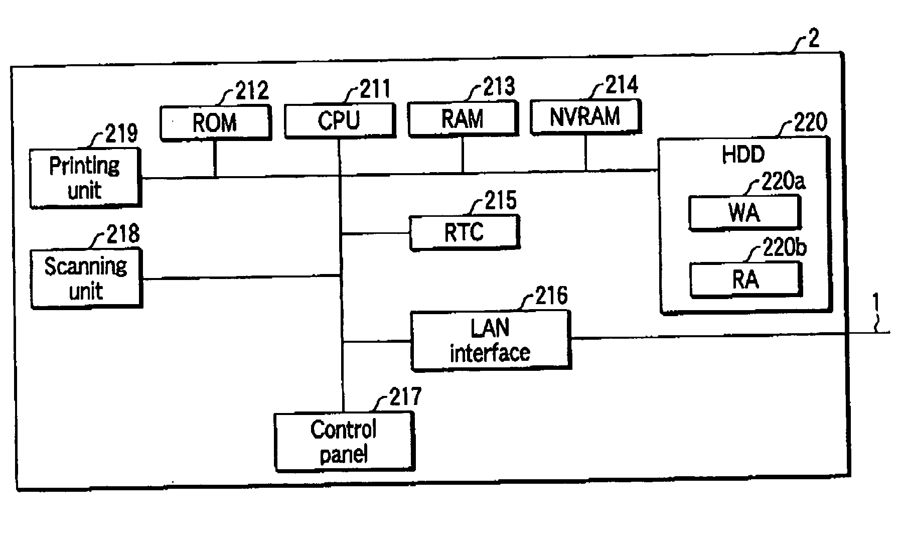
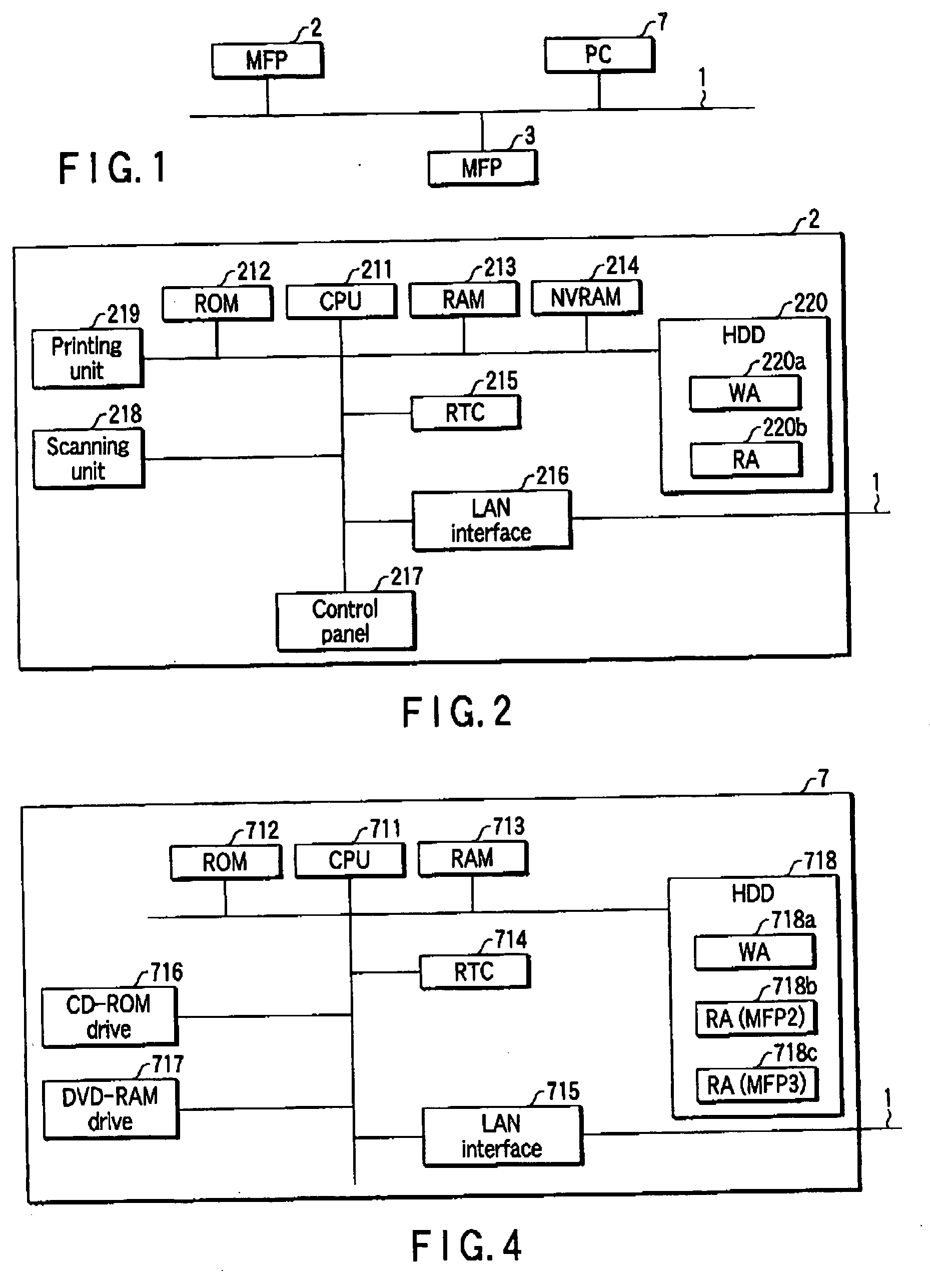
[0052]FIG. 1 is a diagram showing a network structure, A local area network (LAN) 1 is connected to a multi-functional peripheral (MFP) 2, an MFP 3, and a personal computer (PC) 7. The MFPs 2, 3 are image processing apparatuses each having a plurality of functions including a copying function, network scanning function, a network printing function and the like.

[0053] Schematic inner structures of the MFPs 2, 3 will be described with reference to FIG. 2. It should be noted that the MFPs 2, 3 have similar constitutions except data stored in an HDD 220, and therefore the drawing of the MFP 3 is omitted.

[0054] The MFP 2 comprises a CPU 211, ROM 212, RAM 213, NVRAM 214, real-time clock (RTC) 215, LAN interface 216, control panel 217, scanning unit 218, printing unit 219, and HDD 220. The CPU 211 generally controls each unit inside the MFP 2. The ROM 212 stores control program or ...


PUM


Abstract

An image processing apparatus including a first memory which stores data indicating working contents concerning image processing, a connection unit communicatably connected to an external apparatus having a second memory which backs up the data indicating the working contents to be stored in the first memory, a backup unit configured to back up the data indicating the working contents to be stored in the first memory by the second memory, and a processing unit configured to perform working concerning the image processing using the second memory in a case where it is not possible to perform the working using the first memory.

Description

BACKGROUND OF THE INVENTION [0001] 1. Field of the Invention [0002] The present invention relates to an image processing apparatus using a large-capacity storage unit in processing an image. [0003] 2. Description of the Related Art [0004] In Jpn. Pat. Appln. KOIAI Publication No. 2003-234863, a data communication apparatus has been described comprising a document information memory accessible only by a facsimile control unit; a facsimile control function unit which backs up reception information stored in the document information memory; and a hard disk accessible by another control unit and connected to an external apparatus such as a computer apparatus via an interface. The data communication apparatus is capable of copying document information backed up by the hard disk to the document information memory and restoring the document information when the document information of the document information memory is accidentally erased. [0005] In this data communication apparatus or the...

Claims


Application Information

Patent Timeline
IPC IPC(8): H04N5/76
CPCH04N1/00347H04N1/0097H04N2201/0094H04N2201/001H04N2201/0039H04N1/32683
Inventor MATSUI, MAKOTO
Owner KK TOSHIBA
Why Eureka
Try Eureka