Light recycling film and display

Inactive Publication Date: 2006-03-16
ROHM & HAAS DENMARK FINANCE
View PDF11 Cites 20 Cited by
  • Summary
  • Abstract
  • Description
  • Claims
  • Application Information

AI Technical Summary

Problems solved by technology

The use of a reflective polarizer for the front polarizer causes a dramatic loss in

Method used


Image

  • Light recycling film and display
  • Light recycling film and display
  • Light recycling film and display

Examples


first embodiment

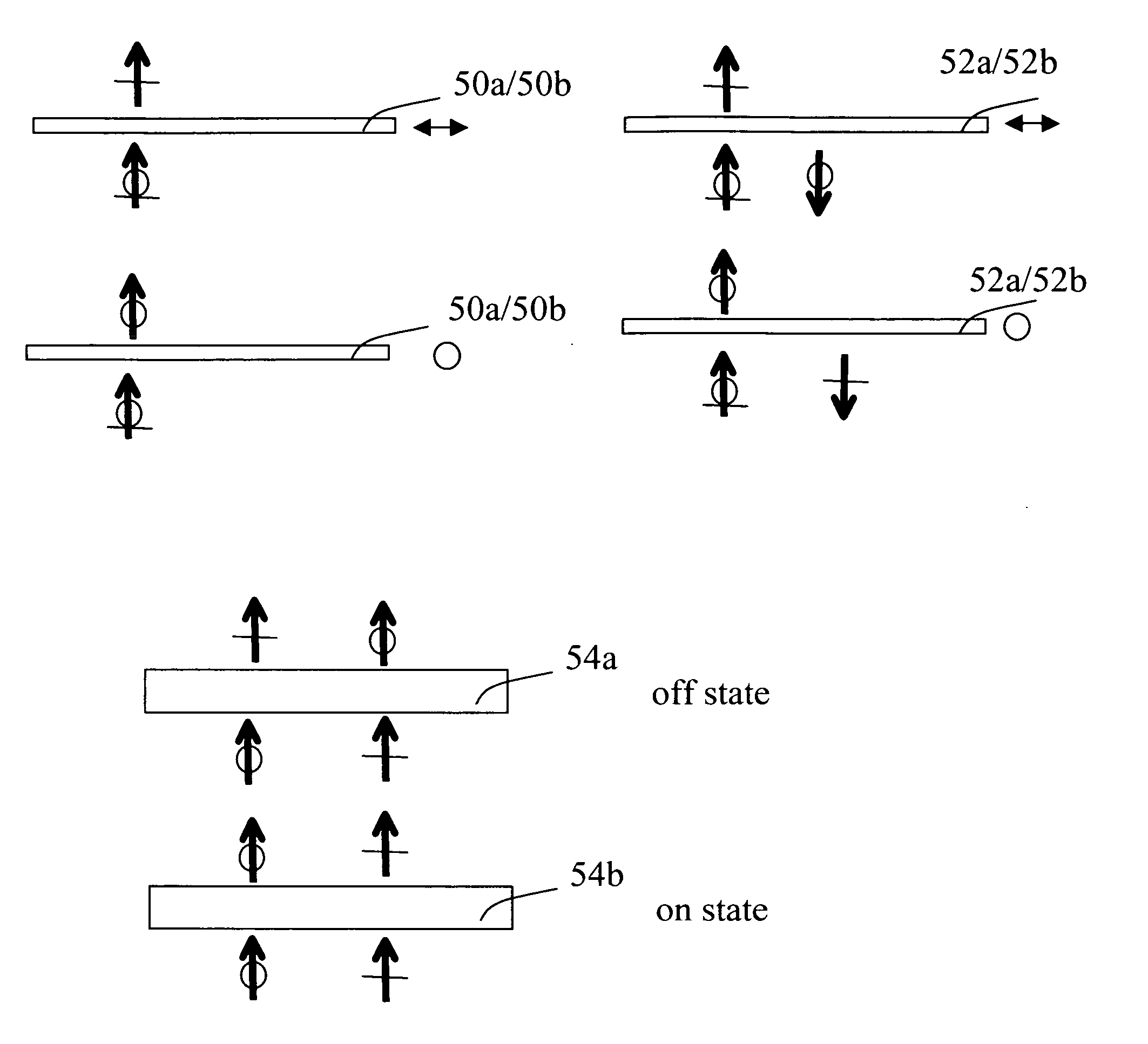
[0086] Referring to FIGS. 3A and 3B, there is shown, for light and dark states respectively, an embodiment of the present invention for an LCD display 20, in which reflective polarizer 52a is disposed between LC component 54a / 54b and front polarizer 50a. Here, the transmission axes of rear and front polarizers 50b and 50a are perpendicular to each other, within ±10 degrees. Following the convention described with reference to FIGS. 1A-1D and 2A-2D, the LC off state converts P-polarization to S-polarization, and S- to P-polarization. The transmission axis of reflective polarizer 52a is parallel to the transmission axis of front polarizer 50a. Recycled light from reflective polarizer 52a has an orthogonal polarization with respect to front polarizer 50a.

[0087]FIG. 3A shows how LC display 20 handles light in the light state. Unpolarized light from backlight unit 56 is incident to rear polarizer 50b that transmits light having S-polarization, absorbing the P-polarization component. Off...

second embodiment

[0091] In the inventive embodiment of FIGS. 3G and 3H, the transmission axes of front and rear polarizers 50a and 50b are parallel to each other, within ±10 degrees. This arrangement may be suitable where on state and off state behavior of LC component 54c / 54d is reversed from that of the preceding examples of FIGS. 1A-3F. Here, off state LC component 54c does not change the polarization of incident light; on state LC component 54d rotates the polarization of incident light. With this optional arrangement, the transmission axis of reflective polarizer 52a must match the transmission axes of both front and rear polarizers 50a and 50b in order to recycle dark state light as shown in FIG. 3H. As with the first embodiment of FIGS. 3A-3D, the embodiment of FIGS. 3G and 3H does not exhibit added contrast degradation due to ambient light.

third embodiment

[0092]FIGS. 4A-4D show an LCD display 30 in an alternate embodiment. Here, a pair of reflective polarizers 52a and 52b is used to improve brightness and efficiency. The handling of light for light and dark states combines the features of the conventional use of a reflective polarizer shown in FIGS. 2A-2D with the inventive embodiment shown in FIGS. 3A-3D. Unpolarized light from backlight unit 56 is incident to rear reflective polarizer 52a that transmits one polarization (S-polarization in FIGS. 4A-4D) and reflects the orthogonal polarization back to backlight unit 56 for recycling. Rear polarizer 50b transmits light having S-polarization, absorbing any residual P-polarization component. Off state LC component 54a rotates the light polarization to provide output light having P-polarization. This light is then transmitted through both reflective polarizer 52a and front polarizer 50a.

[0093]FIG. 4B shows how LC display 30 handles light in the dark state. On state LC component 54b perf...


PUM


Abstract

A liquid crystal device display (20) has a backlight unit (56) for providing illumination, a rear polarizer (50b) disposed proximate the backlight unit (56) for receiving the incident illumination and transmitting substantially polarized illumination, a liquid crystal spatial light modulator for forming a display beam by selective, pixel-wise modulation of the polarization of the substantially polarized illumination, and a reflective polarizer (52a) disposed between the liquid crystal spatial light modulator and a front polarizer (50a).

Description

CROSS REFERENCE TO RELATED APPLICATIONS [0001] The present application is a continuation-in-part of application Ser. No. 10 / 939,656, filed Sep. 13, 2004 entitled “Dark State Light Recycling Film and Display” by Xiang-Dong Mi.FIELD OF THE INVENTION [0002] This invention generally relates to LCD displays using polarizers and more particularly relates to an LCD display using a reflective polarizer to recycle white, gray scale, or dark state light that otherwise is absorbed by the front polarizer of the LCD. BACKGROUND OF THE INVENTION [0003] Conventional Liquid Crystal Device (LCD) displays form images by modulating the polarization state of illumination that is incident to the display surface. In a typical back-lit LCD display, an arrangement of polarizers is used to support the LCD modulation, including a rear polarizer, between the LCD and the light source, to provide polarized light to the LCD spatial light modulator and a front polarizer, acting as an analyzer. (By definition, the...

Claims


Application Information

Patent Timeline
IPC IPC(8): G02F1/135
CPCG02F1/133528G02F1/133536G02F1/1336G02F1/1397G02F2001/133507G09G2360/16G02F2001/133562G02F2001/133567G02F2203/66G09G3/3406G02F2001/133531G02F1/133507G02F1/133531G02F1/133562G02F1/133567
Inventor MI, XIANG-DONGNOTHHARD, GARY E.
Owner ROHM & HAAS DENMARK FINANCE
Why Eureka
Try Eureka