Substrate for liquid crystal display and liquid crystal display having the same

a technology of liquid crystal display and substrate, which is applied in the direction of magnetotherapy using permanent magnets, instruments, etc., can solve the problems of degrading display quality, degrading display quality, and difficult to evenly disperse spacers, and achieve high display quality

Active Publication Date: 2006-03-16
AU OPTRONICS CORP
View PDF10 Cites 19 Cited by
  • Summary
  • Abstract
  • Description
  • Claims
  • Application Information

AI Technical Summary

Benefits of technology

[0020] The invention makes it possible to provide a liquid crystal display which can achieve high display quality.

Problems solved by technology

However, spacers dispersed within a pixel can cause an alignment defect of the liquid crystal and leakage of light.
An alignment defect or leakage of light results in a reduction of contract or glare on the display screen, which degrades display quality.
Further, increases in the size of substrates have made it difficult to disperse spacers evenly.
When spacers are unevenly dispersed, the cell thickness between the substrates can vary to result in irregularities of luminance.
However, when the pillar spacers 150 are too hard, the pillar spacers 150 cannot be sufficiently shrunk even if they are pressed at the predetermined pressure.
As a result, the liquid crystal is moved toward a lower part of the panel by gravity, and an irregularity is therefore caused by gravity in that the cell thickness becomes greater in the lower part.
When the pillar spacers 150 are too soft, since they undergo a great amount of displacement and also a great amount of plastic deformation in response to a pressure from the outside, an irregularity of the cell thickness can occur.
As thus described, there is a problem in that it is difficult to fabricate a liquid crystal display in which no gravity-originated irregularity occurs and no bubble is generated at a low temperature and which exhibits high resistance to pressures from the outside to achieve high display quality.

Method used


Image

  • Substrate for liquid crystal display and liquid crystal display having the same
  • Substrate for liquid crystal display and liquid crystal display having the same
  • Substrate for liquid crystal display and liquid crystal display having the same

Examples


embodiment 1-1

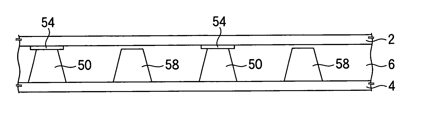
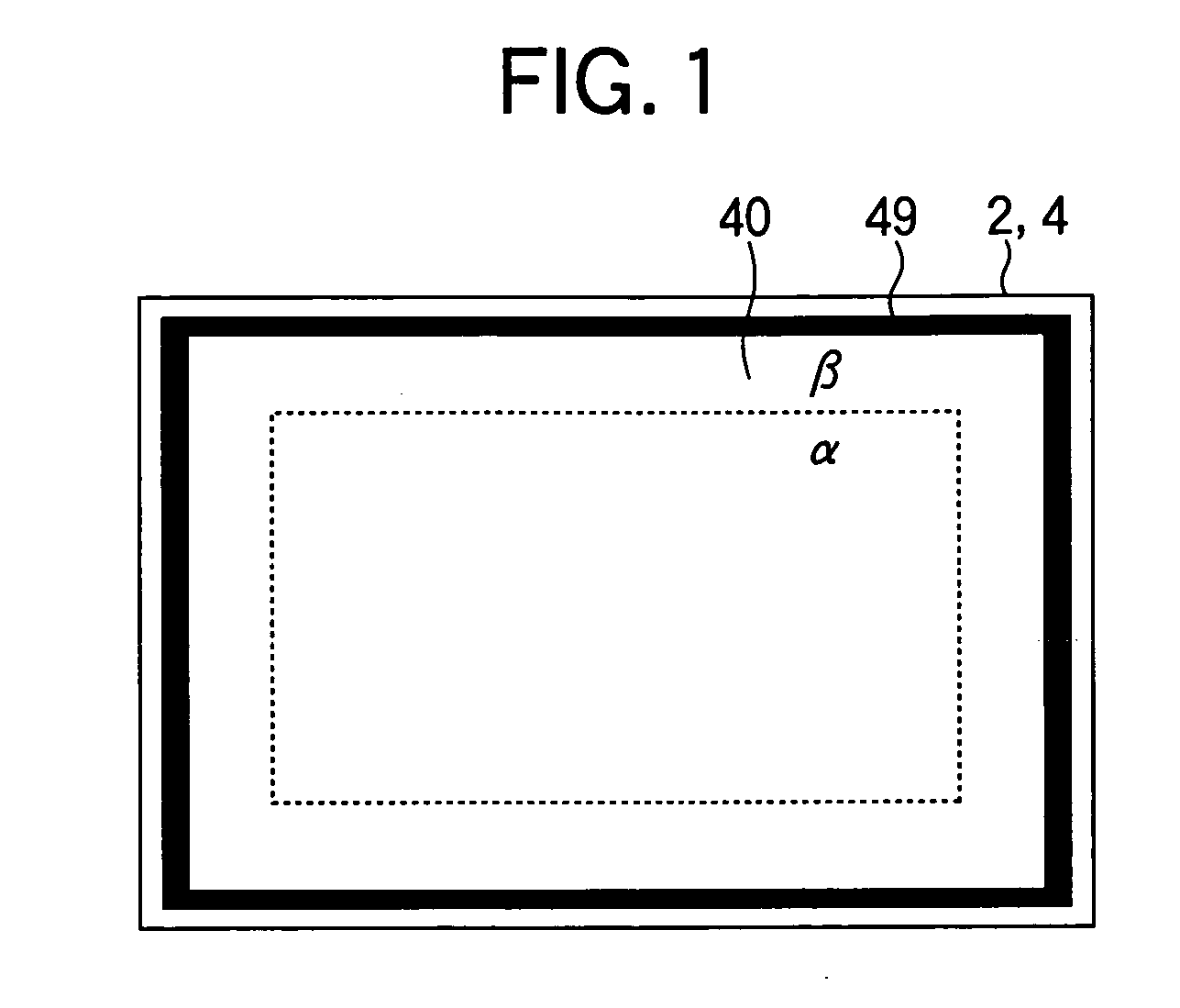
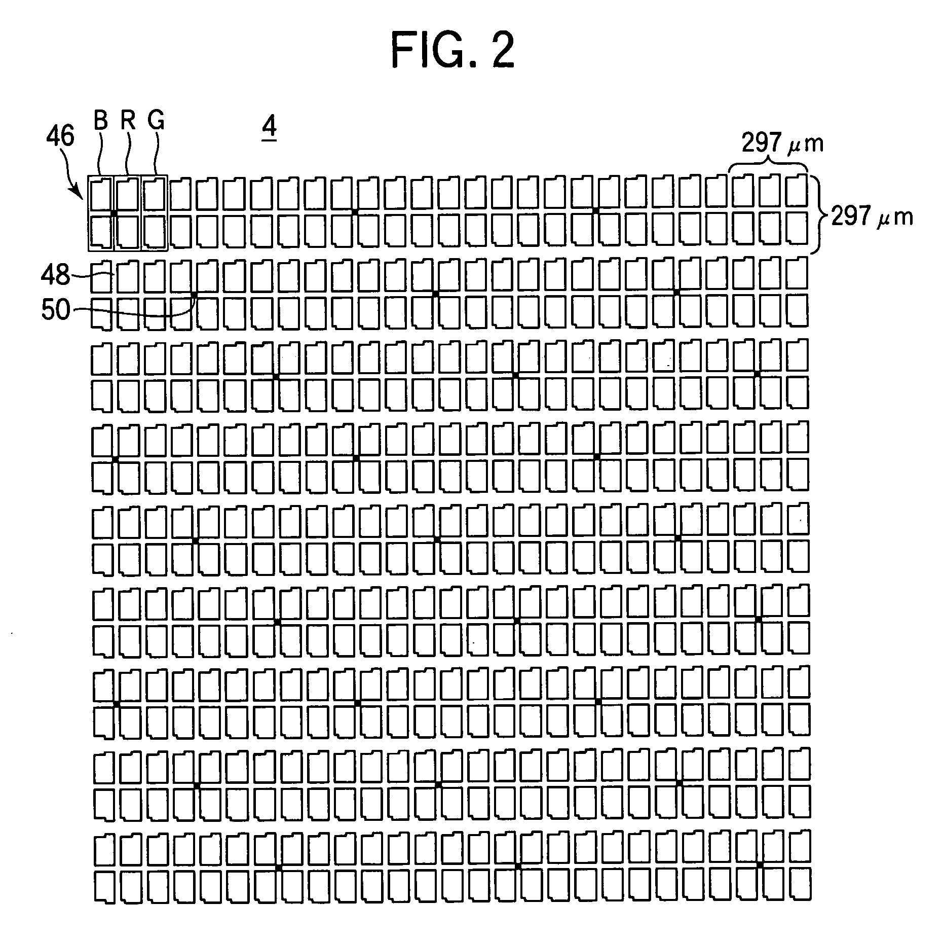
[0042] A liquid crystal display according to Embodiment 1-1 in the present mode for carrying out the invention will now be described. A CF substrate was fabricated by forming color filter layers in respective colors R, G and B, and a common electrode on a glass substrate and thereafter forming a plurality of pillar spacers 50 in the form of a truncated cone having an upper base surface 51 with a diameter of 10 μm and a lower base surface 52 with a diameter of 20 μm as shown in FIG. 4. The disposition density of the pillar spacers 50 was one per three pixels (nine sub-pixels) in a region a in the neighborhood of the center of a display area 40 and one per four pixels (twelve sub-pixels) in a region β in the neighborhood of a picture-frame area. Thereafter, an alignment film was formed on a surface of the CF substrate and on a surface of a TFT substrate which was fabricated at a separate step. Subsequently, steps such as rubbing, sealing material application, substrate combining, pane...

embodiment 2-1

[0045] A liquid crystal display according to Embodiment 2-1 in the present mode for carrying out the invention will be described. FIG. 5 shows a schematic configuration of the liquid crystal display of the present embodiment, and FIGS. 6A to 6D show schematic configurations of pillar spacers 50. As shown in FIG. 5, a display area 40 is divided into four regions α, β, γ and δ which are arranged in the order listed in the top-to-bottom direction of the display area when the liquid crystal is erected. Pillar spacers 50a in the form of a truncated cone having an upper base surface 51a with a diameter of 14 μm and a lower base surface 52a with a diameter of 24 μm are formed in the uppermost region α as shown in FIG. 6A. Pillar spacers 50b in the form of a truncated cone having an upper base surface 51b with a diameter of 12 μm and a lower base surface 52b with a diameter of 22 μm are formed in the region β under the region a as shown in FIG. 6B. Pillar spacers 50c in the form of a trunca...

embodiment 2-2

[0049] A liquid crystal display according to Embodiment 2-2 in the present mode for carrying out the invention will now be described. FIG. 9 shows a schematic configuration of the liquid crystal display of the present embodiment. As shown in FIG. 9, a display area 40 is divided into sixteen regions α, β, γ, δ, γ, β, α, . . . , α, β, γ and β which are arranged in the order listed in the top-to-bottom direction of the liquid crystal panel when the panel is erected. Pillar spacers 50a to 50d similar to those in Embodiment 2-1 are formed in the regions α to δ, respectively. In the case of a liquid crystal display having a large-sized screen, when the screen is divided into four regions as shown in FIG. 5, a region δ in which pillar spacers 50 undergo a great compressive displacement will have a great area, and an irregularity in the cell thickness will be more apt to occur. Therefore, in the liquid crystal display having a large-sized screen, the region δ is preferably distributed as sh...


PUM

PropertyMeasurementUnit
diameteraaaaaaaaaa
diameteraaaaaaaaaa
diameteraaaaaaaaaa

Abstract

The invention relates to a substrate for a liquid crystal display used as a display portion of an electronic apparatus and a liquid crystal display having the same and provides a substrate for a liquid crystal display which allows high display quality to be achieved and a liquid crystal display having the same. The substrate has a TFT substrate and a CF substrate provided opposite to each other, pillar spacers formed on the CF substrate to maintain a cell gap between the substrates, a region α which is located in the neighborhood of the center of a display area and in which the pillar spacers are compressed in a first amount of compressive displacement when a predetermined pressure in a direction perpendicular to a substrate surface is applied, and a region β which is located in the neighborhood of a picture-frame area outside the above region α and in which the pillar spacers are compressed in a second amount of compressive displacement greater than the first amount of compressive displacement.

Description

BACKGROUND OF THE INVENTION [0001] 1. Field of the Invention [0002] The present invention relates to a substrate for a liquid crystal display used in a display section of an electronic apparatus and a liquid crystal display having the same. [0003] 2. Description of the Related Art [0004] In general, a liquid crystal display has two substrates each having transparent electrodes and a liquid crystal sandwiched between the substrates. The liquid crystal display is enabled for display in a desired manner by applying a predetermined voltage between the transparent electrodes to drive the liquid crystal and to thereby control light transmittance at each pixel. Recently, there is increasing demand for liquid crystal displays, which has diversified requirements for liquid crystal displays. Above all, improvement of display quality is strongly demanded. [0005] Presently, active matrix type liquid crystal displays having a thin film transistor (TFT) at each pixel as a switching element (TFT-L...

Claims


Application Information

Patent Timeline
Patent Type & Authority Applications(United States)
IPC IPC(8): G02F1/1339
CPCG02F2001/13396G02F1/13394G02F1/13396A44C7/004A61H39/04A61N2/002A61N2/006A61N2/06
Inventor SAWASAKI, MANABUFUJIKAWA, TETSUYA
Owner AU OPTRONICS CORP
Why Eureka
Try Eureka