Lighting device and image display unit and light guide provided with it

a technology of light guide and image display unit, which is applied in the direction of lighting and heating apparatus, instruments, polarising elements, etc., can solve the problems of inability to meet the requirements of phase plate structure, and inability to meet the requirements of phase plate practical specifications, etc., to achieve the effect of improving light utilization efficiency, reducing light utilization efficiency, and reducing display quality (contrast ratio)

Inactive Publication Date: 2006-03-16
SHARP KK
View PDF13 Cites 10 Cited by
  • Summary
  • Abstract
  • Description
  • Claims
  • Application Information

AI Technical Summary

Benefits of technology

[0075] In the first illumination device according to the present invention, the lightguide element includes a polarization selection layer for causing light of a specific polarization direction, among the light incident from the incidence surface, to selectively go out from the outgoing surface, and a polarization conversion layer for converting light of a polarization direction, different from the specific polarization direction, into the light of the specific polarization direction. Accordingly, the light incident on the inside of the lightguide element from the light source via the incidence surface can be caused to go out efficiently as light of the specific polarization direction. Therefore, the light utilization efficiency is improved. In addition, the polarization selection layer reflects the light of the specific polarization direction substantially only toward the outgoing surface. Therefore, the reduction in the light utilization efficiency and the reduction in the display quality (contrast ratio), which are caused by light reflection toward the counter surface (toward the viewer in a front light), can be suppressed.
[0101] The fourth lightguide element according to the present invention includes a polarization selection layer for causing light of a specific polarization direction, among the light incident from the incidence surface, to selectively go out from the outgoing surface, and a polarization conversion layer for converting light of a polarization direction, different from the specific polarization direction, into the light of the specific polarization direction. Accordingly, the light incident on the inside of the lightguide element from the light source via the incidence surface can be caused to go out efficiently as light of the specific polarization direction. Therefore, the light utilization efficiency is improved. In addition, the polarization conversion layer is a phase plate. Therefore, the slow axis thereof is uniform (the same) in a plane parallel to the outgoing surface Accordingly, the efficiency at which the light is converted into the light of the specific polarization direction is generally uniform in a plane parallel to the outgoing surface. Therefore, it is easy to provide a design in which the light of the specific polarization direction goes out uniformly from the outgoing surface. Furthermore, the directions of the slow axis and the fast axis of the phase plate in a plane parallel to the outgoing surface do not match the specific polarization direction. Therefore, the phase plate preferably acts as a polarization conversion layer.

Problems solved by technology

However, the illumination devices described above have the following problems.
Considering that the liquid crystal displays will become thinner in the future, such a structure is not practical.
However, Japanese Laid-Open Patent Publication No. 9-218407 describes no practical specifications of the phase plate 932, for example, the anisotropy of the refractive index, thickness, and the direction of the optical axis (slow axis or fast axis).
When the illumination device 900 is used as a front light, light goes out toward the viewer and thus the display quality is deteriorated.
As described above, an illumination device capable of causing light from a light source to go out as light of a specific polarization direction sufficiently efficiently has not been developed.

Method used


Image

  • Lighting device and image display unit and light guide provided with it
  • Lighting device and image display unit and light guide provided with it
  • Lighting device and image display unit and light guide provided with it

Examples


embodiment 1

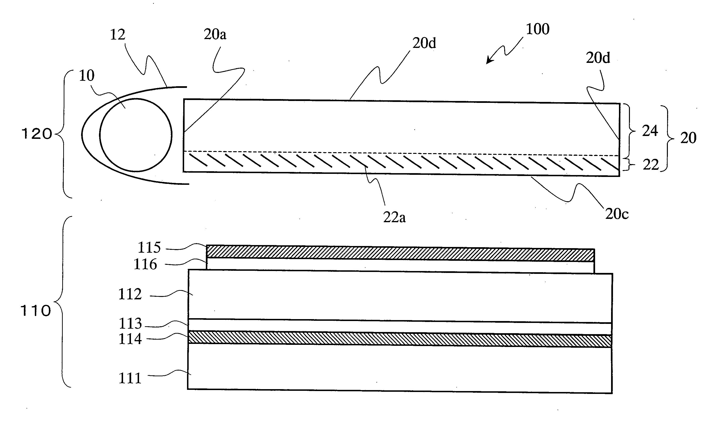
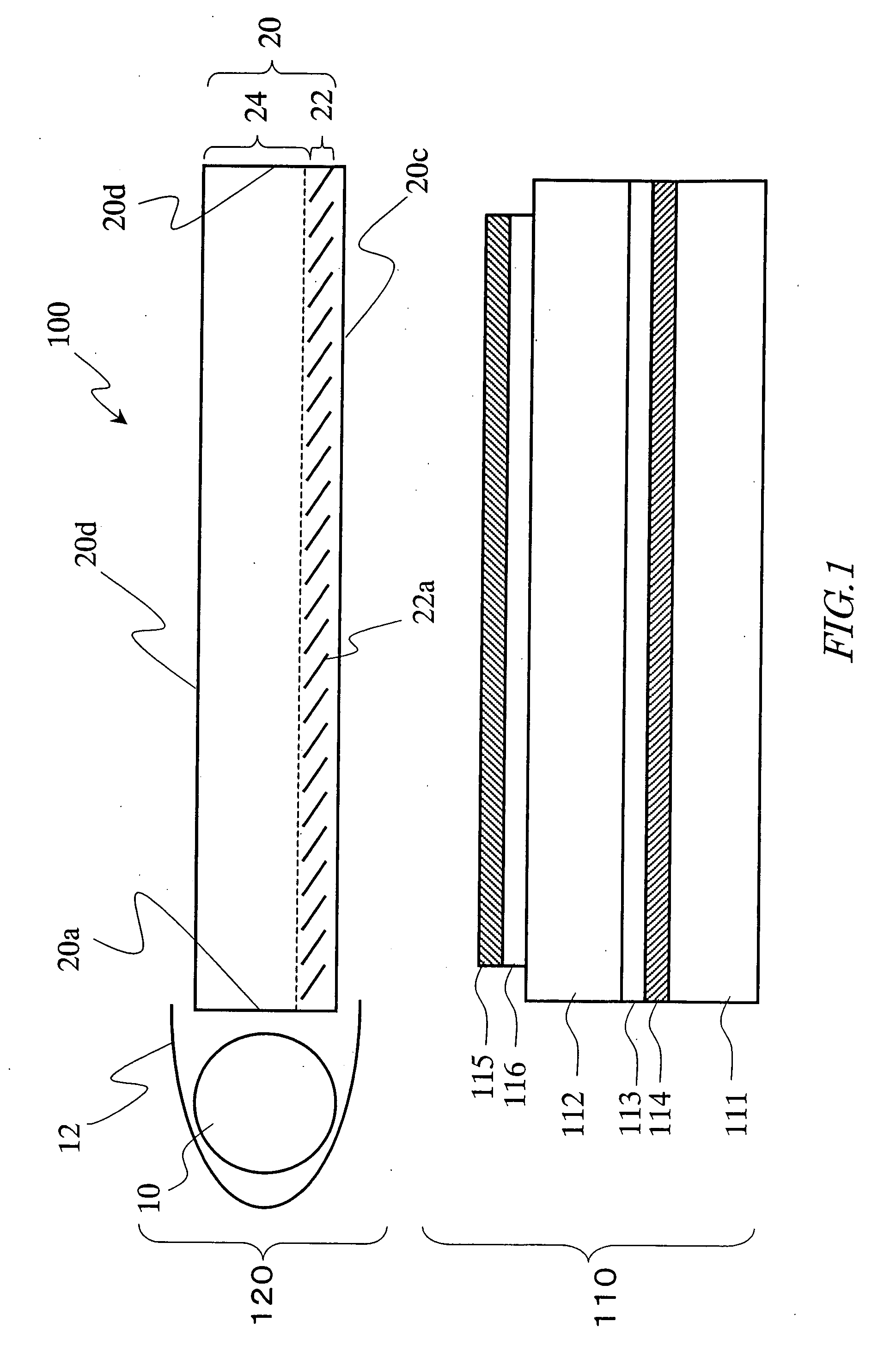
[0151] First, with reference to FIG. 1, a structure of an illumination device 120 in an embodiment according to the present invention and a structure of a liquid crystal display (image display apparatus) 100 including the same will be described.

[0152] As shown in FIG. 1, the liquid crystal display 100 is a reflection type liquid crystal display including a reflection type liquid crystal display panel 110 and the illumination device (front light) 120.

[0153] The reflection type liquid crystal display panel 110 is a known reflection type liquid crystal display panel, and includes a pair of substrates (for example, glass substrates) 111 and 112 and a liquid crystal layer 113 provided therebetween in this embodiment. A reflection electrode 114 is provided on the liquid crystal layer 113 side of the rear-side substrate 111. A transparent electrode (not shown) is provided on the liquid crystal layer 113 side of the viewer-side substrate 112. A polarizer (typically, a polarization plate) ...

embodiment 2

[0183] With reference to FIG. 5, a structure of an illumination device 220 in an embodiment according to the present invention and a structure of a liquid crystal display (image display apparatus) 200 including the same will be described. In the figures referred to below, elements having substantially the same functions to those of the elements in the illumination device 120 and the liquid crystal display 100 in Embodiment 1 bear the identical reference numerals thereto, and descriptions thereof will be partially omitted, for the sake of simplicity of description.

[0184] As shown in FIG. 5, the liquid crystal display 200 is a reflection type liquid crystal display including a reflection type liquid crystal display panel 210 and the illumination device (front light) 220.

[0185] The reflection type liquid crystal display panel 210 is a known reflection type liquid crystal display panel, and has, for example, the same structure as that of the reflection type liquid crystal display pane...

embodiment 3

[0231] With reference to FIG. 25, a structure of an illumination device 320 in an embodiment according to the present invention and a structure of a liquid crystal display (image display apparatus) 300 including the same will be described.

[0232] As shown in FIG. 25, the liquid crystal display 300 is a reflection type liquid crystal display including a reflection type liquid crystal display panel 310 and the illumination device (front light) 320.

[0233] The reflection type liquid crystal display panel 310 is a known reflection type liquid crystal display panel, and has, for example, the same structure as that of the reflection type liquid crystal display panel 110 of the liquid crystal display 100 in Embodiment 1.

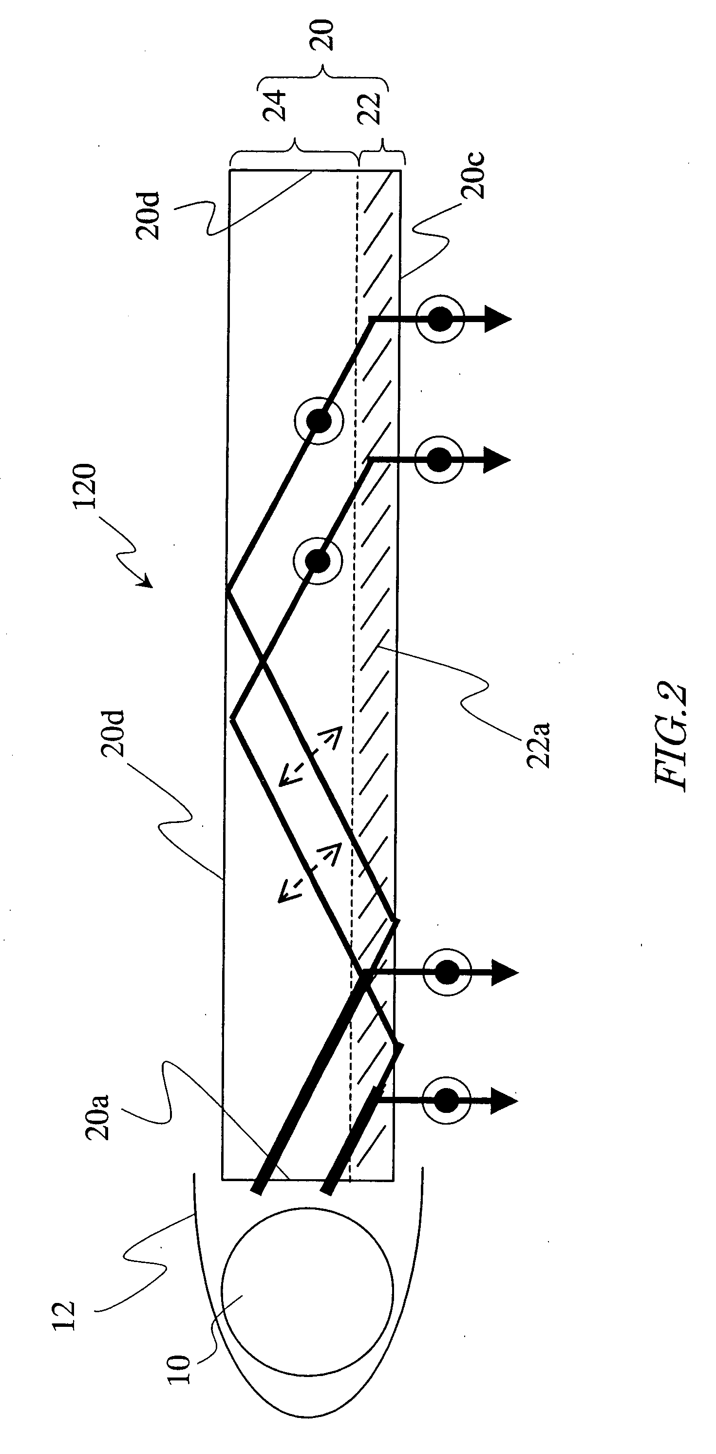
[0234] The lightguide element 20 of the illumination device 320 includes the polarization selection layer 22 located in the vicinity of the outgoing surface 20c and the polarization conversion layer 24 located on the counter surface 20d side of the lightguide element 20. I...


PUM

PropertyMeasurementUnit
thicknessaaaaaaaaaa
thicknessaaaaaaaaaa
thicknessaaaaaaaaaa

Abstract

An illumination device according to the present invention includes a light source; and a lightguide element including an incidence surface for receiving light emitted from the light source and an outgoing surface from which the light incident from the incidence surface goes out. The lightguide element includes a polarization selection layer for causing light of a specific polarization direction (first polarized light), among the light incident from the incidence surface, to selectively go out from the outgoing surface, and a polarization conversion layer for converting second polarized light, polarized in a different direction from that of the first polarized light, into the first polarized light. The polarization selection layer reflects the first polarized light substantially only toward the outgoing surface.

Description

TECHNICAL FIELD [0001] The present invention relates to an illumination device, an image display apparatus including the same, and a lightguide element, and more particularly relates to an illumination device having a high light utilization efficiency, an image display apparatus including the same, and a lightguide element. BACKGROUND ART [0002] Recently, liquid crystal displays have been widely used for, for example, office automation devices such as word processors and personal computers, mobile information devices such as PDAs, and camera-equipped VTRs including liquid crystal monitors owing to their features of being thin and consuming low power. [0003] Unlike light emitting displays such as CRTs (cathode ray tubes), PDPs (plasma display panels) and EL (electroluminescence) devices, non-light emitting displays represented by liquid crystal displays do not emit light themselves but control a transmitted amount or a reflected amount of externally emitted light to display character...

Claims


Application Information

Patent Timeline
Patent Type & Authority Applications(United States)
IPC IPC(8): F21V7/04F21V8/00G02B5/30G02B6/00G02F1/13357
CPCG02B5/3025G02B6/0001G02F1/13362G02B6/0056G02B6/0038G02B6/0025G02F1/133528
Inventor MASUDA, TAKESHI
Owner SHARP KK
Why Eureka
Try Eureka