Fault detection system for inverter

a fault detection and inverter technology, applied in the direction of dc-ac conversion without reversal, process and machine control, instruments, etc., can solve problems such as abnormal detection, and achieve the effect of increasing the usage rate of the bus voltag

Active Publication Date: 2006-03-16
MITSUBISHI ELECTRIC CORP
View PDF3 Cites 29 Cited by
  • Summary
  • Abstract
  • Description
  • Claims
  • Application Information

AI Technical Summary

Benefits of technology

[0010] The present invention is proposed to solve the above problems, and a first object thereof is to provide an inverter fa...

Problems solved by technology

If the resulting values do not fit in the range, it is detected as abnormal.
The problem here is that, due to the above-described structure, such a conventional fault ...

Method used


Image

  • Fault detection system for inverter
  • Fault detection system for inverter
  • Fault detection system for inverter

Examples


first embodiment

[0021] In the below, a first embodiment of the present invention is described by referring to the accompanying drawings.

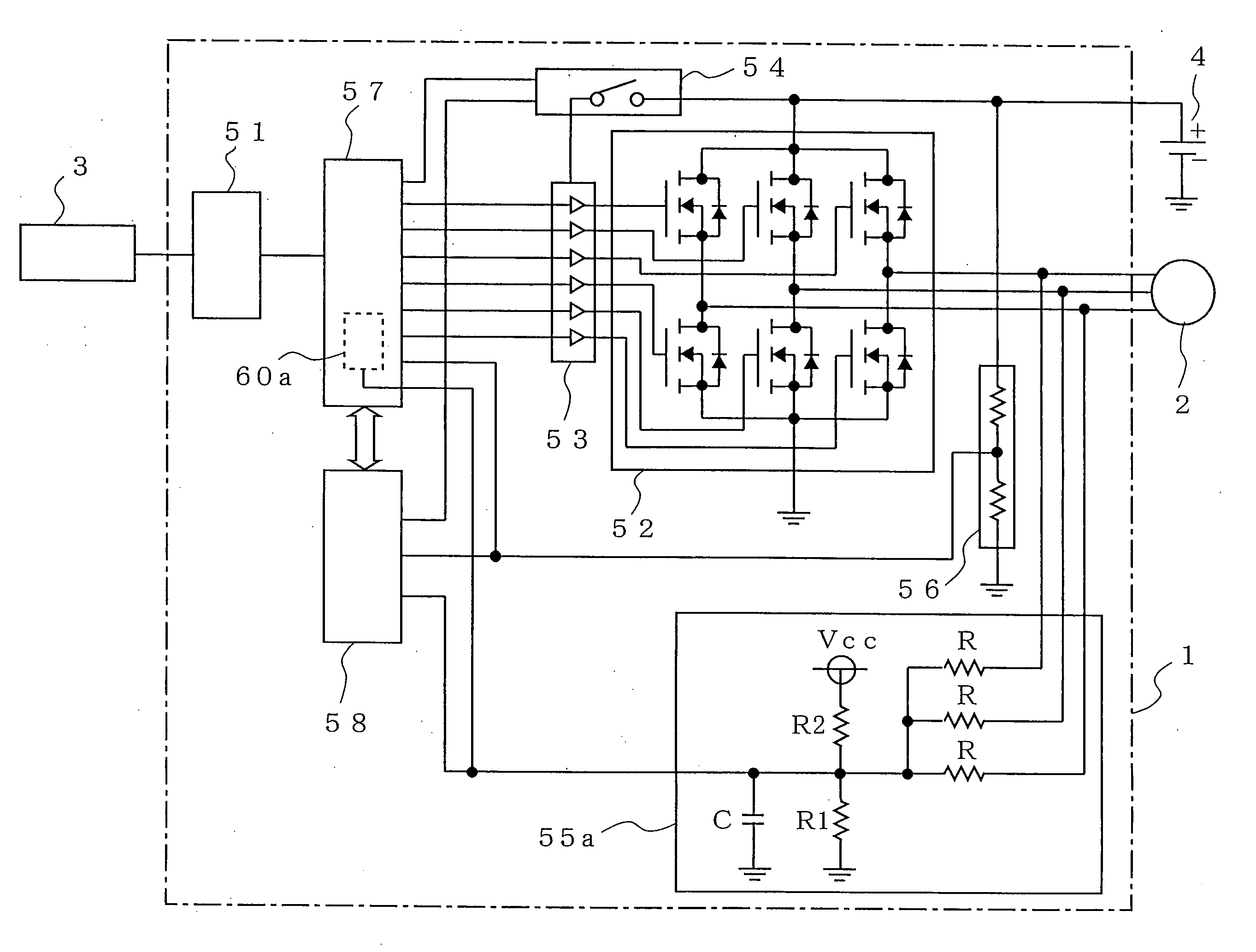
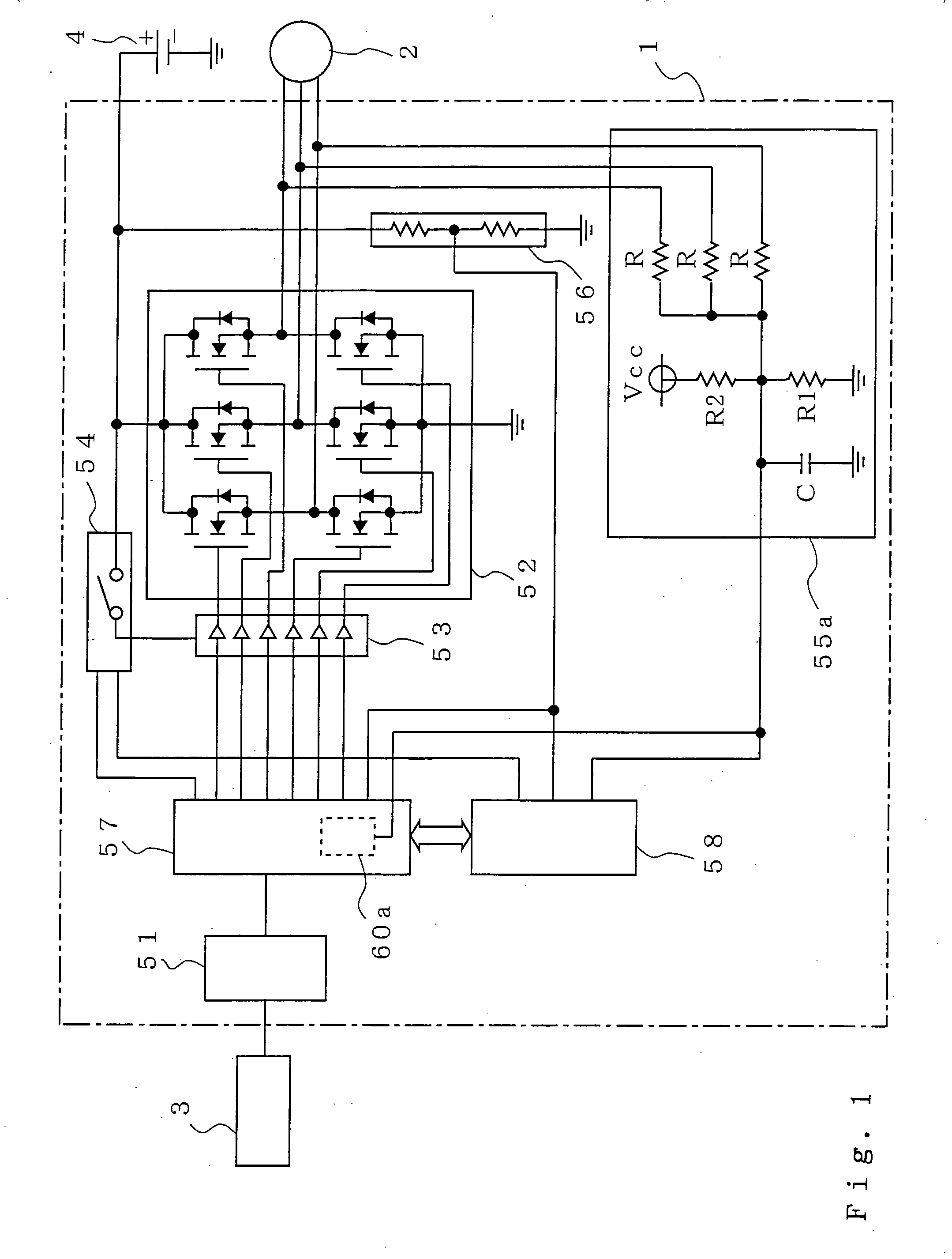
[0022]FIG. 1 is a block diagram showing an exemplary structure of an inverter fault detection system of a first embodiment when it is applied to a motor controller.

[0023] In the drawing, a reference numeral 1 denotes a controller, and 2 denotes a motor for in-car use (three-phase motor). In this embodiment, used for the motor 2 is a DC brushless motor.

[0024] A reference numeral 3 denotes a rotor angle sensor for detecting a rotor angle of the motor 2 for phase excitation in accordance with the magnetic pole of the motor 2. A reference numeral 4 denotes a battery.

[0025] A reference numeral 51 denotes an input interface for forwarding, to the controller 1, a rotor angle signal detected by the rotor angle sensor 3. A reference numeral 52 denotes a three-phase PWM (Pulse Width Modulation) inverter provided for driving the motor 2, and 53 denotes a gate drive circui...

second embodiment

[0072] In the above-described first embodiment, the sum value of the phase voltages is used as a basis to determine whether the three-phase PWM inverter is in the faulty state. Alternatively, the line voltage may be used as a basis for such fault determination.

[0073] This effectively enables constant fault determination for the three-phase PWM inverter in either drive mode of the first embodiment, i.e., the first and second drive modes.

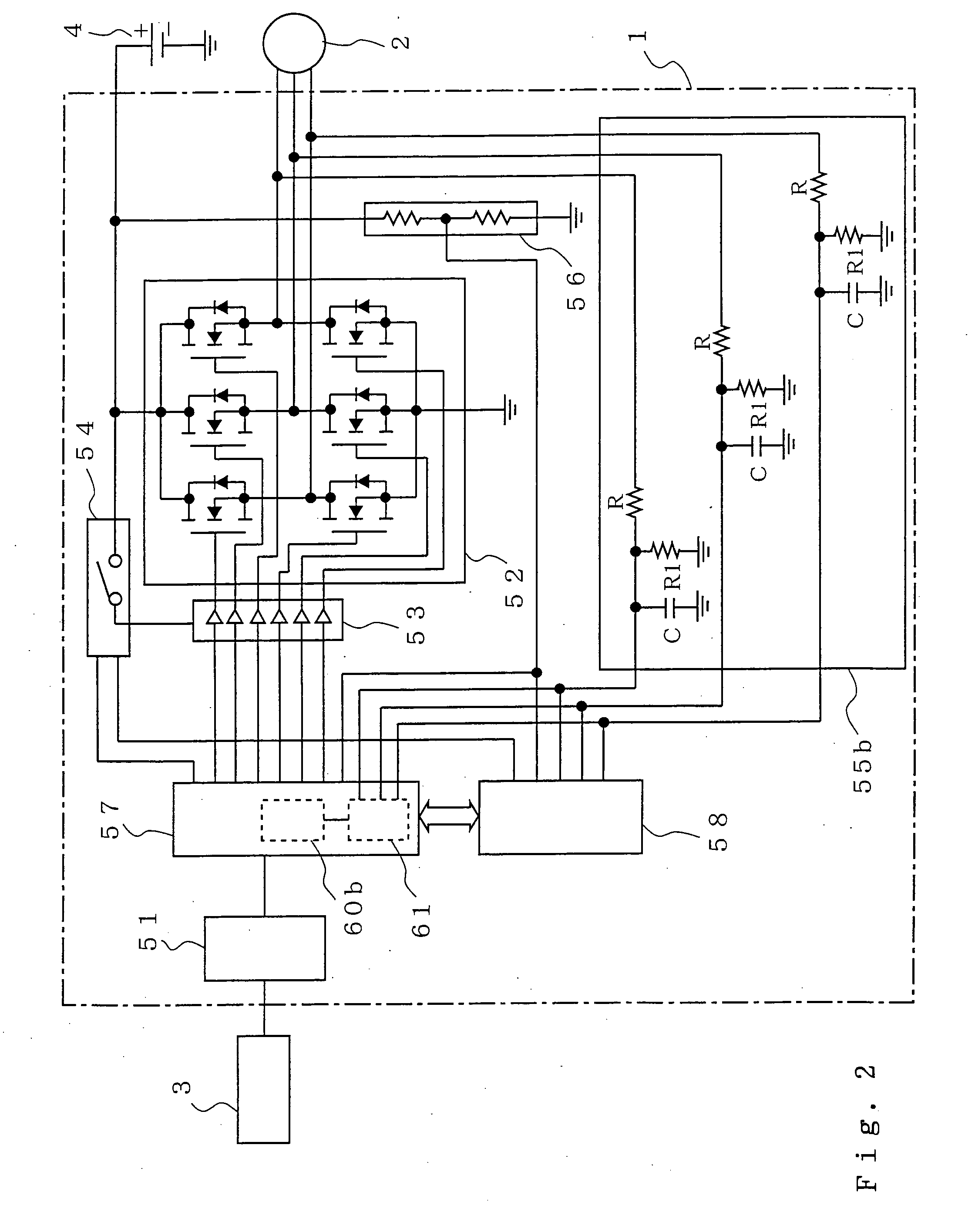
[0074]FIG. 2 is a block diagram showing an exemplary structure of an inverter fault detection system of a second embodiment when it is applied to a motor controller for in-car use.

[0075] In the drawing, a reference numeral 55b denotes an output voltage monitor circuit (output voltage monitor means), 60b denotes fault determination means, and 61 denotes line voltage sum means.

[0076] Note that, in the drawing, if components share the same reference numeral as those in FIG. 1, it means that those are the same or substantially operating the same as th...


PUM


Abstract

An inverter fault detection system of the present invention is provided with: bus voltage monitor means for monitoring the bus voltage of a three-phase inverter; output voltage monitor means for summing the phase output voltages coming from the three-phase PWM inverter, and for outputting the resulting summed output voltage through a filter having a low-pass characteristic of passing through only the cutoff frequency lower than the PWM carrier frequency; and fault determination means for determining that the three-phase PWM inverter is in the faulty state when the output voltage coming from the output voltage monitor means is almost the same as the voltage value corresponding to 3/2 times of the bus voltage monitored by the bus voltage monitor means.

Description

BACKGROUND OF THE INVENTION [0001] 1. Field of the Invention [0002] The present invention relates to a fault detection system for detecting faults occurring in an inverter, e.g., three-phase PWM inverter. [0003] 2. Description of the Related Art [0004] An exemplary conventional fault detection system used for a three-phase power converter (three-phase inverter) is found in Japanese Patent No. 2902455 (Publication No: JP-A-4-87553). The fault detection system is provided with a detector, a sample hold circuit, a multiplexer, an A / D converter, and a micro processor. Specifically, the detector is provided to detect three-phase voltage and current relating to the three-phase power converter, and analog signals of the three-phase voltage and current detected by the detector are sample-hold by the sample hold circuit. The analog signals of the three-phase voltage and current are also output from the multiplexer responsively to the sequential selection made on a signal basis. Thus selected...

Claims


Application Information

Patent Timeline
IPC IPC(8): H02J1/00H02M7/48H02M7/5387
CPCH02M1/32H02M7/53873H02M7/5387G01R31/281
Inventor KIFUKU, TAKAYUKIMATSUSHITA, MASAKI
Owner MITSUBISHI ELECTRIC CORP
Why Eureka
Try Eureka