Image forming apparatus

a technology of forming apparatus and forming chamber, which is applied in the direction of electrographic process apparatus, instruments, optics, etc., can solve the problem of moving space for the printer unit, and achieve the effect of improving the workability of maintenance and improving the exchange rate of toner

Active Publication Date: 2006-03-16
SEIKO EPSON CORP
View PDF6 Cites 28 Cited by
  • Summary
  • Abstract
  • Description
  • Claims
  • Application Information

AI Technical Summary

Benefits of technology

[0020] With this structure, the user can make use of a large space above the printer unit in a state where the upper casing and cover have been lifted, and workability for maintenance such as removal of the jammed sheets or exchange of the toner will be improved.

Problems solved by technology

However, in the structure where the rack for holding the scanner unit is a separate body from the printer unit, and the printer unit must be pulled out from underneath of the top plate of the rack on each occasion of performing maintenance, for example, removal of jammed sheets or replenishment of toner, there has been such a problem that a moving space for the printer unit must be kept around the image forming apparatus.

Method used


Image

  • Image forming apparatus
  • Image forming apparatus
  • Image forming apparatus

Examples


first embodiment

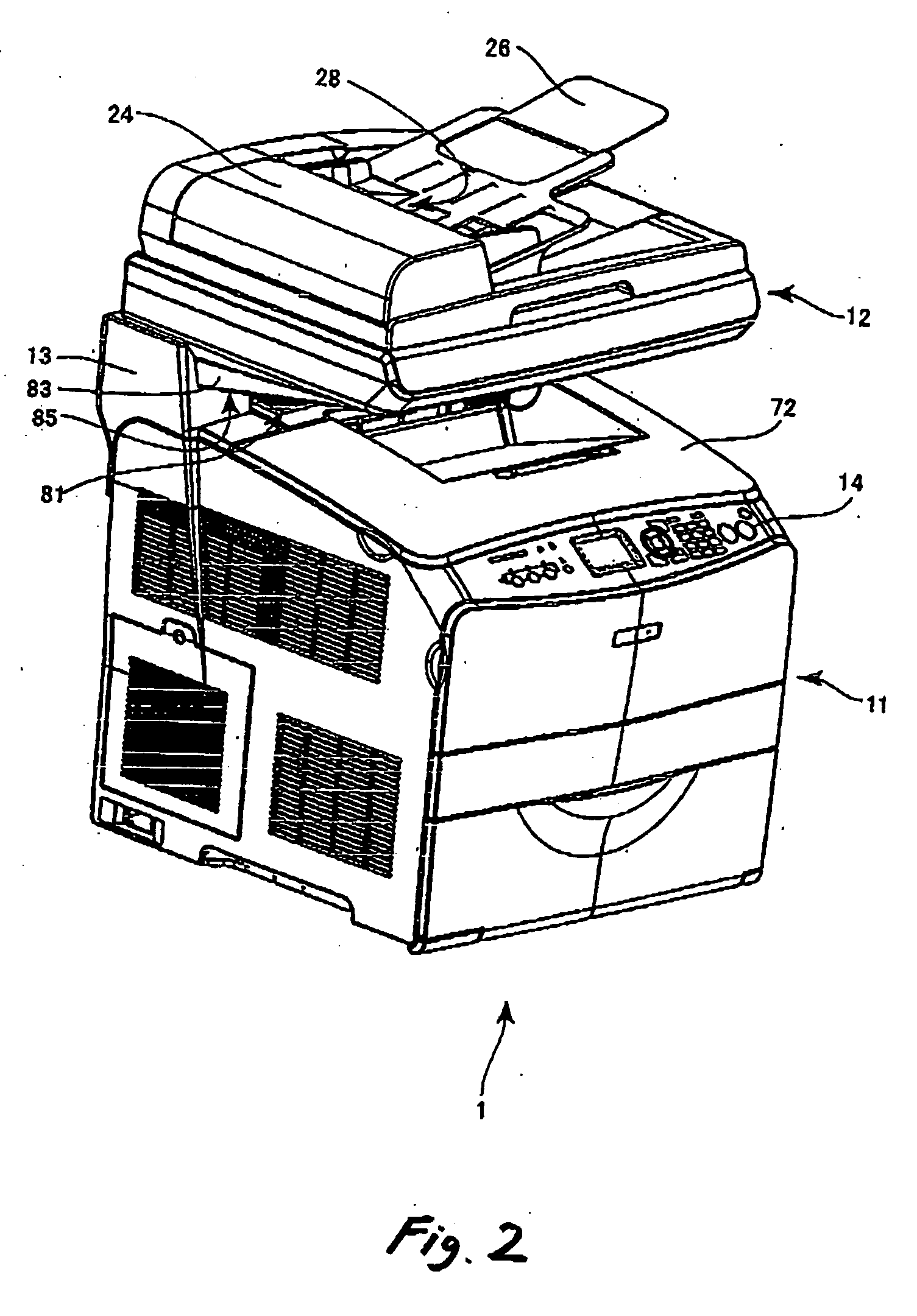
[0037]FIG. 2 is a perspective view showing an external appearance of a hybrid machine 1 as an image forming apparatus according to the invention. The hybrid machine 1 includes a scanner unit 12 for reading an original, an ASF (Automatic Sheet Feeding) unit 24, a printer unit 11 for printing an image which has been read, and props 13. The scanner unit 12 is pivotably connected to upper parts of the props 13. The props 13 are fixed to an upper part of the printer unit 11 so as to tiltably support the scanner unit 12. It is to be noted that the props 13 need not be fixed to the printer unit 11, but may be independently provided on an installation plane of the hybrid machine 1.

[0038]FIG. 3 is a schematic view showing an interior structure of the scanner unit 12. A box-shaped scanner casing 20 as an upper casing is open in its upper part, and connected to the props 13 so as to pivot by hinges, which are not shown. An original table 22 is a transparent glass plate which covers the opening...

second embodiment

[0052]FIGS. 11A and 11B are front views and side views of the scanner unit 12 and the ASF unit 24 of the hybrid machine 1, as an image forming apparatus according to the invention. As shown in FIG. 11A, the projection 80 for preventing flexure of the scanner casing 20 is a piece of projection which covers almost all part of the bottom of the scanner casing 20. The side walls 83 of the projection 80 are in a shape of a triangular plate, extending in parallel with each other from the front end to the back end of the scanner casing 20 and at a right angle with respect to the plane 90 including the table face of the original table 22. Therefore, the lower end wall 82 in a front part of the projection 80 has a flat face inclined downwardly in a direction from the front face to the back face of the hybrid machine 1. Moreover, the lower end wall 82 in the front part of the projection 80 may be formed with a curved face having an upward convex shape, as shown in FIG. 11B.

third embodiment

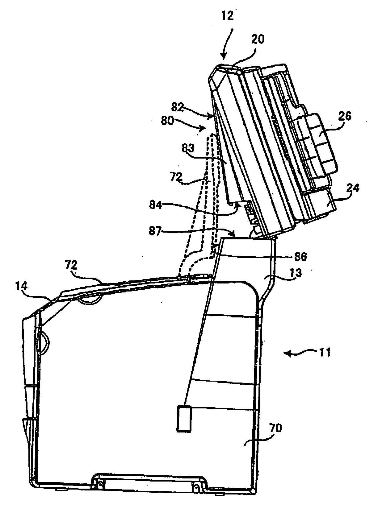
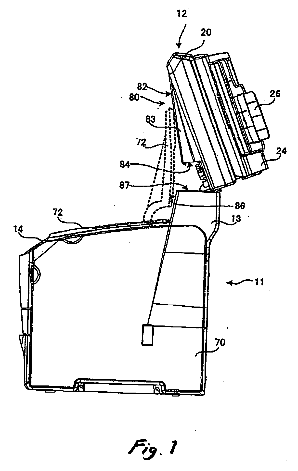
[0053]FIG. 12 is a schematic side view of the hybrid machine 1, as an image forming apparatus according to the invention. The back end wall 84 of the projection 80 provided on the bottom face of the scanner casing 20 is inclined downwardly in a forward direction from a position near a hinge 95 which connects the scanner casing 20 to the prop 13, in a horizontal state of the original table 22. Because the back end wall 84 of the projection 80 is abutted against the front end face 86 of the prop 13, the scanner unit 12 is supported in such a manner that the plane 90 including the table face of the original table 22 may be horizontally kept.


PUM


Abstract

A prop is extending from the printer unit upwards. A rear end portion of an upper casing is coupled with an upper portion of the prop pivotably in a vertical direction. A transparent platen is provided on a top face of the upper casing. An image capturer is provided in the upper casing and operable to capture an image on an original disposed on the platen and to output image data. A projection is provided on a bottom face of the upper casing and is extending in a front-rear direction of the upper casing. The projection has a rear end face adapted to be supported by the prop when the upper casing is placed in a first position causing the platen to extend horizontally. The rear end face extends obliquely in a forward-downward direction.

Description

BACKGROUND OF THE INVENTION [0001] The present invention relates to an image forming apparatus. [0002] As an image forming apparatus including a printer and an image scanner which can be operated independently or under control of a personal computer (PC), such as a so-called hybrid machine, there has been known such a structure that a scanner unit is mounted on a top plate of a rack, and a printer unit provided with a caster is installed below the top plate. When an original such as a bound book is to be read, a user will strongly press the original against an original table for enhancing tightness of contact between the original and the original table. For this reason, the top plate on which the scanner unit is mounted, and a connecting structure between the top plate and a prop are required to have high rigidity. [0003] By holding the scanner unit on the top plate of the rack, it is possible to secure a space above the printer unit and to eject printed sheets of paper onto an uppe...

Claims


Application Information

Patent Timeline
Patent Type & Authority Applications(United States)
IPC IPC(8): G03G15/00
CPCG03G15/60
Inventor KARASAWA, TAKASHINAKAZAWA, TORUMIYAWAKI, TSUYOSHI
Owner SEIKO EPSON CORP
Why Eureka
Try Eureka