Supercharge Your Innovation With Domain-Expert AI Agents!

Method and device for confinement of a liquid

a liquid confinement and liquid technology, applied in the field of liquid confinement, can solve the problems of inability to accurately fill the small cavity of the micro-dispenser, inability to obtain the accurate level of liquid, and inability to use the optical actuator to fill the small volum

Inactive Publication Date: 2006-03-16
COMMISSARIAT A LENERGIE ATOMIQUE ET AUX ENERGIES ALTERNATIVES
View PDF5 Cites 2 Cited by
  • Summary
  • Abstract
  • Description
  • Claims
  • Application Information

AI Technical Summary

Benefits of technology

The present invention solves the problem of automatically and collectively filling cavities on a substrate with a liquid and maintaining the level of the liquid at a stable position. The invention uses a surface treatment to create areas on the substrate with larger wettability than the surrounding areas, allowing the liquid to be confined in these areas. The treated areas may have rough features and may be lipophobic or hydrophobic depending on the liquid used. The invention also includes a device for confining a liquid in a cavity on the substrate.

Problems solved by technology

It should further be noted that a micro-dispenser is neither suitable for accurately filling small cavities nor for obtaining an accurate level of liquid.
Therefore, it is unusable for filling an optical actuator, the operation of which substantially depends on the level of a meniscus.

Method used


Image

  • Method and device for confinement of a liquid
  • Method and device for confinement of a liquid
  • Method and device for confinement of a liquid

Examples


Embodiment Construction

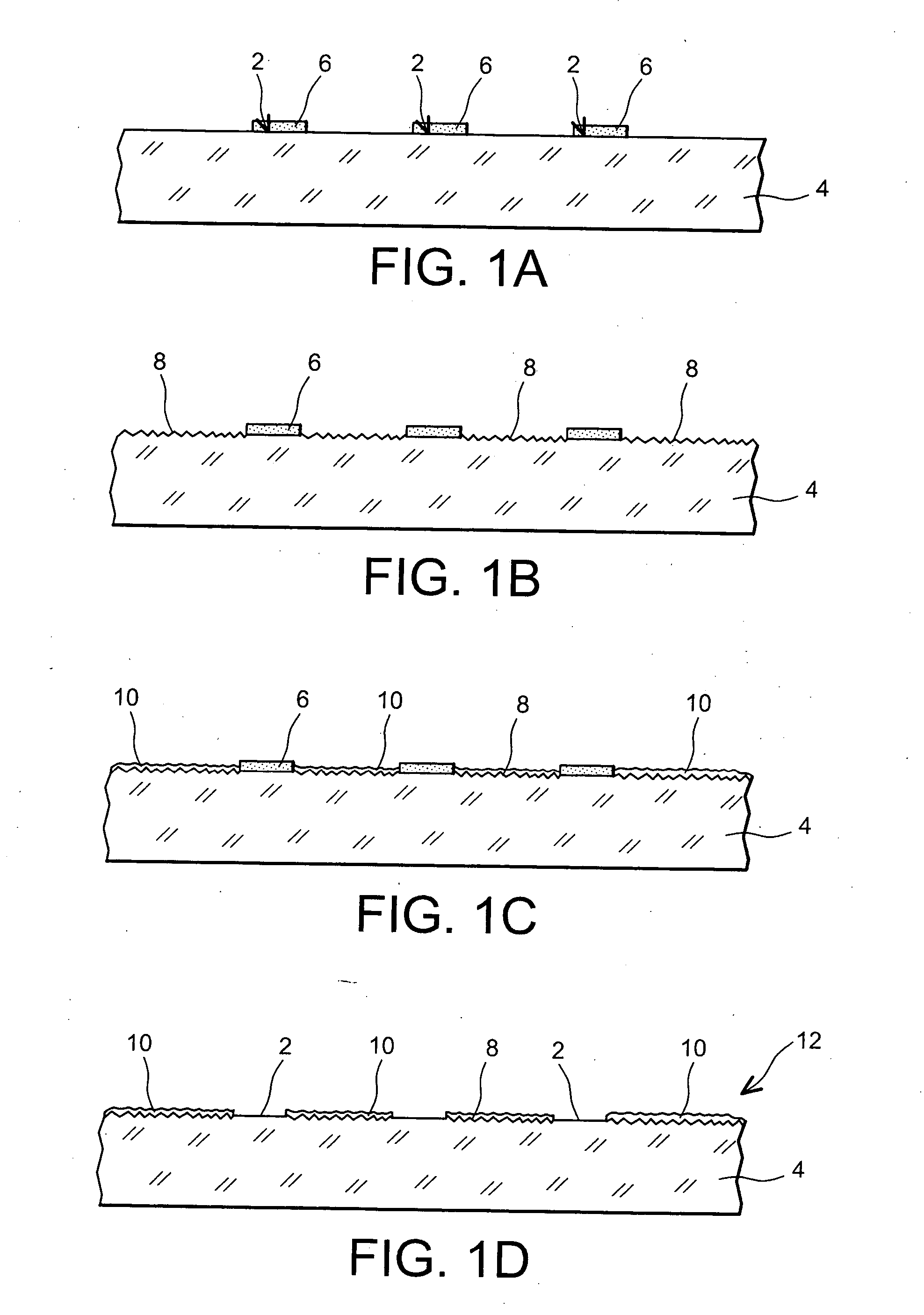
[0045] A first example of the method, object of the invention, is now described.

[0046] In this first example, the intention is to confine an oil, for example an optical oil (an oil with a determined optical index), in areas 2 of a hydrophobic substrate 4, for example in silicon (FIG. 1A).

[0047] To do this, a photoresist layer 6 is formed on each of these areas. Next, on the surroundings of these areas, a lipophobic material layer is formed.

[0048] However, beforehand, in order to enhance the lipophobicity of these surroundings, it is preferable to form on the latter, rough features 8 (FIG. 1B), the size of which is of the order of 1 μm for example, and which are called microscopic rough features.

[0049] In order to form these microscopic rough features, one proceeds in the following way: the microscopic rough features may be obtained by etching silicon through a non-homogeneous native oxide. Microscopic rough features are thereby formed by the etching selectivity between silicon a...


PUM


Abstract

According to the invention, in order to confine a liquid in at least one area of a substrate, a treatment is applied to the surface of the substrate, creating, on this surface, at least one area (54), the wettability of which is larger than that of the surroundings of the area, the substrate is immersed in the liquid, and then it is removed from the latter. Further, after applying the treatment to the surface, a cavity (40) intended to contain the liquid and including a single aperture (41) is formed in the area. The invention is particularly applicable to the filling of cavities of an optical micro-actuator.

Description

TECHNICAL FIELD [0001] The present invention relates to a method and device for confining a liquid. [0002] It is particularly applicable [0003] to air actuators and to optical actuators, [0004] to electrocapillarity or thermocapillarity fluid actuators and, more generally, [0005] to any actuator or sensor which uses a liquid either as a motor or as a transducer, or as an active or ambient medium. [0006] In particular, the invention is applicable to actuators or to sensors which are intended to contain a liquid. It is also applicable to the assaying or conditioning of a liquid, more specifically in the case when limitation of the localization of this liquid is required. [0007] The invention is for example applicable to the manufacturing of a micro-actuator of the kind known from the following document: [0008] [1] WO 02 / 48777A, published on Jun. 20, 2002, “an optical micro-actuator, an optical component using the micro-actuator, and method for making an optical micro-actuator”, invent...

Claims


Application Information

Patent Timeline
Patent Type & Authority Applications(United States)
IPC IPC(8): B05D5/00B05D1/18B01L3/00G02B6/35
CPCB01L3/5085B01L3/5088G02B6/3538B01L2300/0819B01L2300/0822B01L2200/0642
Inventor DIVOUX, CLAIREORTIZ, LAURENT
Owner COMMISSARIAT A LENERGIE ATOMIQUE ET AUX ENERGIES ALTERNATIVES
Features
  • R&D
  • Intellectual Property
  • Life Sciences
  • Materials
  • Tech Scout
  • Unparalleled Data Quality
  • Higher Quality Content
  • 60% Fewer Hallucinations
Learn More