
Toner

Active Publication Date: 2006-03-16
CANON KK
View PDF9 Cites 20 Cited by
  • Summary
  • Abstract
  • Description
  • Claims
  • Application Information

AI Technical Summary

Benefits of technology

[0011] The present invention aims at providing a toner excellent in low-temperature fixability and storage stability, and capable of providing a high image density without causing fogging or toner fusion even in long-term use.

Problems solved by technology

For example, when attention is paid to a printer, a ratio of power consumption in a fixing step to the total power consumption is considerably large, and an increase in fixing temperature inevitably increases power consumption.
Furthermore, a high fixing temperature involves a problem such as the curling of paper which is to be printed out, so a reduction in fixing temperature has been strongly desired.
However, toner containing such releasing agent is apt to deteriorate owing to high degree of duration, although the toner has an expanded temperature region in which fixation can be performed.
In addition, the durability of the toner may be insufficient for long-term stable use.
However, only an approach based on a releasing agent hardly provides toner performance that can sufficiently cope with recent trends, in other words, an increase in speed of a printer and energy savings.
However, none of those conventional toners has sufficiently achieved compatibility between durability in long-term use and low-temperature fixability, and each of them is still susceptible to improvement in terms of storage stability.
In particular, when an image forming process speed is high, the time during which toner and a fixing unit are in contact with each other upon fixation is extremely short, so the amount of heat that the toner receives is limited.

Method used


Image

  • Toner
  • Toner
  • Toner

Examples


example 1

Production of Toner 1

[0217] 450 parts of a 0.1-mol / l aqueous solution of Na3PO4 were charged into 720 parts of ion-exchanged water, and the whole was heated to 60° C. After that, 67.7 parts of a 1.0-mol / l aqueous solution of CaCl2 were added to prepare an aqueous medium containing a dispersion stabilizer.

[0218] Meanwhile, the following formulations were uniformly dispersed and mixed by means of an ATTRITOR (manufactured by Mitsui Miike Machinery Co., Ltd.). The dispersed mixture was heated to 60° C., and 10 parts of paraffin wax (highest endothermic peak in DSC 78° C., Mn=500, Mw=660) were added to, mixed with, and dissolved into the mixture. 4.5 parts of 2,2′-azobis(2,4-dimethyl-valeronitrile) as a polymerization initiator were dissolved into the resultant to produce a polymerizable monomer composition.

Styrene74partsn-butyl acrylate26partsDivinyl benzene0.5partPolyester component 15partsPolyester component 85partsNegative charge control agent (T-771part(manufactured by Hodogaya...

example 2

Production of Toner 2

[0222] A toner 2 was produced in the same manner as in the production of the toner 1 except that: the polyester component 2 was used instead of the polyester component 1; and the reaction time after the temperature increase up to 90° C. was changed to 30 minutes.

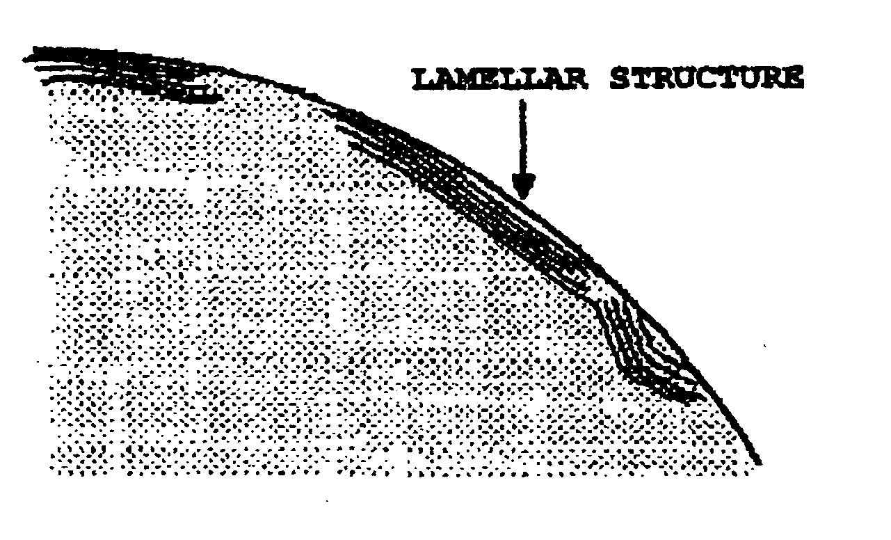
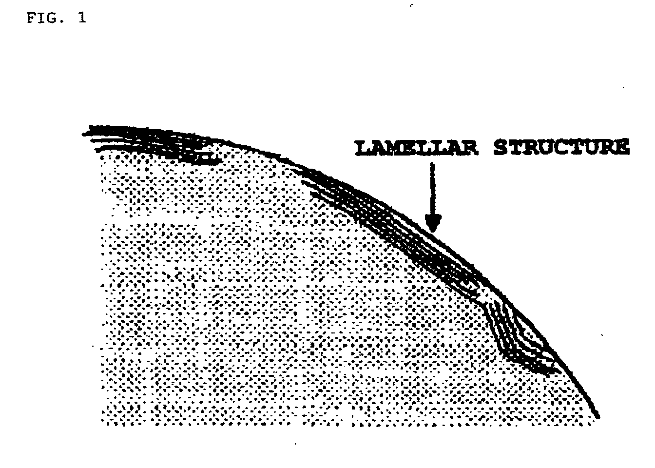
[0223] The cross section of the toner 2 was observed by means of a TEM. As a result, each of the surface layer and inside of the toner was observed to have the lamellar structure of the added polyester. Table 2 shows the physical properties of the toner 2.

example 3

Production of Toner 3

[0224] A toner 3 was produced in the same manner as in the production of the toner 1 except that the polyester component 3 was used instead of the polyester component 1.

[0225] The cross section of the toner 3 was observed by means of a TEM. As a result, each of the surface layer and inside of the toner was observed to have the lamellar structure of the added polyester. Table 2 shows the physical properties of the toner 3.


PUM

PropertyMeasurementUnit
Temperatureaaaaaaaaaa

Abstract

An object of the present invention is to provide a toner excellent in durability and storage stability, and having good fixing performance in a wide fixing temperature region even at a high process speed. According to the present invention, there is provided a toner containing: a binder resin; a colorant; and a polyester resin, in which: I) the polyester resin contains at least, as a main component, polyester obtained by subjecting a monomer composition containing an alcohol selected from aliphatic diols each having 2 to 22 carbon atoms and a carboxylic acid selected from aliphatic dicarboxylic acids each having 2 to 22 carbon atoms to a polycondensation reaction; and II) a region having a lamellar structure is present at a surface layer of the toner.

Description

BACKGROUND OF THE INVENTION [0001] 1. Field of the Invention [0002] The present invention relates to a toner to be used for developing an electrostatic latent image to be formed in an image forming method such as an electrophotographic method, an electrostatic recording method, a magnetic recording method, or a toner jet recording method. [0003] 2. Description of the Related Art [0004] A large number of methods have been conventionally known as electrophotographic methods. A general electrophotographic method involves the steps of: using a photoconductive substance to form an electrostatic latent image on an electrostatic charge image-bearing member (which may hereinafter be referred to as the “photosensitive member”) through various means; developing the latent image with toner to form a toner image which is transferred as required onto a recording medium such as paper; and fixing the toner image onto the recording medium by means of heat, pressure, or the like to produce a copied ...

Claims


Application Information

Patent Timeline
IPC IPC(8): G03G9/08
CPCG03G9/0825G03G9/0827G03G9/08797G03G9/08795G03G9/08755G03G9/08
Inventor YANASE, ERIKOMAGOME, MICHIHISAMATSUI, TAKASHISAKAKIBARA, AKIRA
Owner CANON KK
Learn More