Testing plate

a technology of testing plate and test tube, which is applied in the field of simple testing plate, can solve the problems of no material which meets such conditions and light becomes a noise, and achieve the effect of accurate fluorescence measuremen

Inactive Publication Date: 2006-03-16
ALPS ALPINE CO LTD
View PDF3 Cites 6 Cited by
  • Summary
  • Abstract
  • Description
  • Claims
  • Application Information

AI Technical Summary

Benefits of technology

[0011] The present invention has been finalized in view of the drawbacks inherent in the conventional testing plate, and it is an object of the present invention to provi

Problems solved by technology

Therefore, there is a problem in that the light becomes a noise when a fluorescent intensity is measured.
However, the resin substrate 31 and the cover 33 need to satisf

Method used


Image

  • Testing plate
  • Testing plate
  • Testing plate

Examples


Embodiment Construction

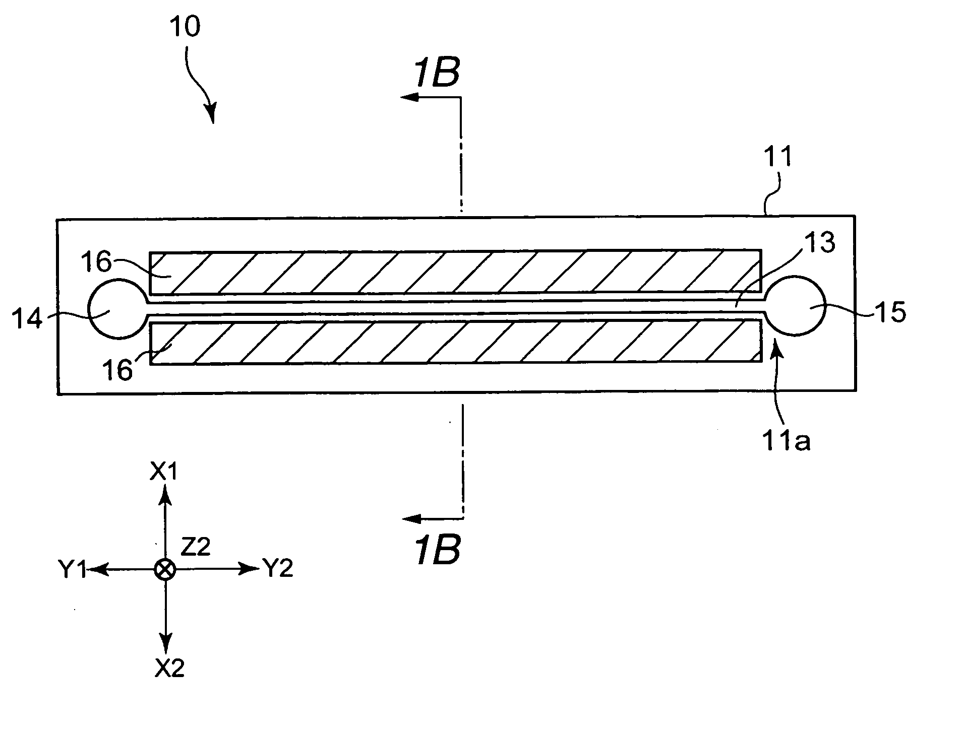
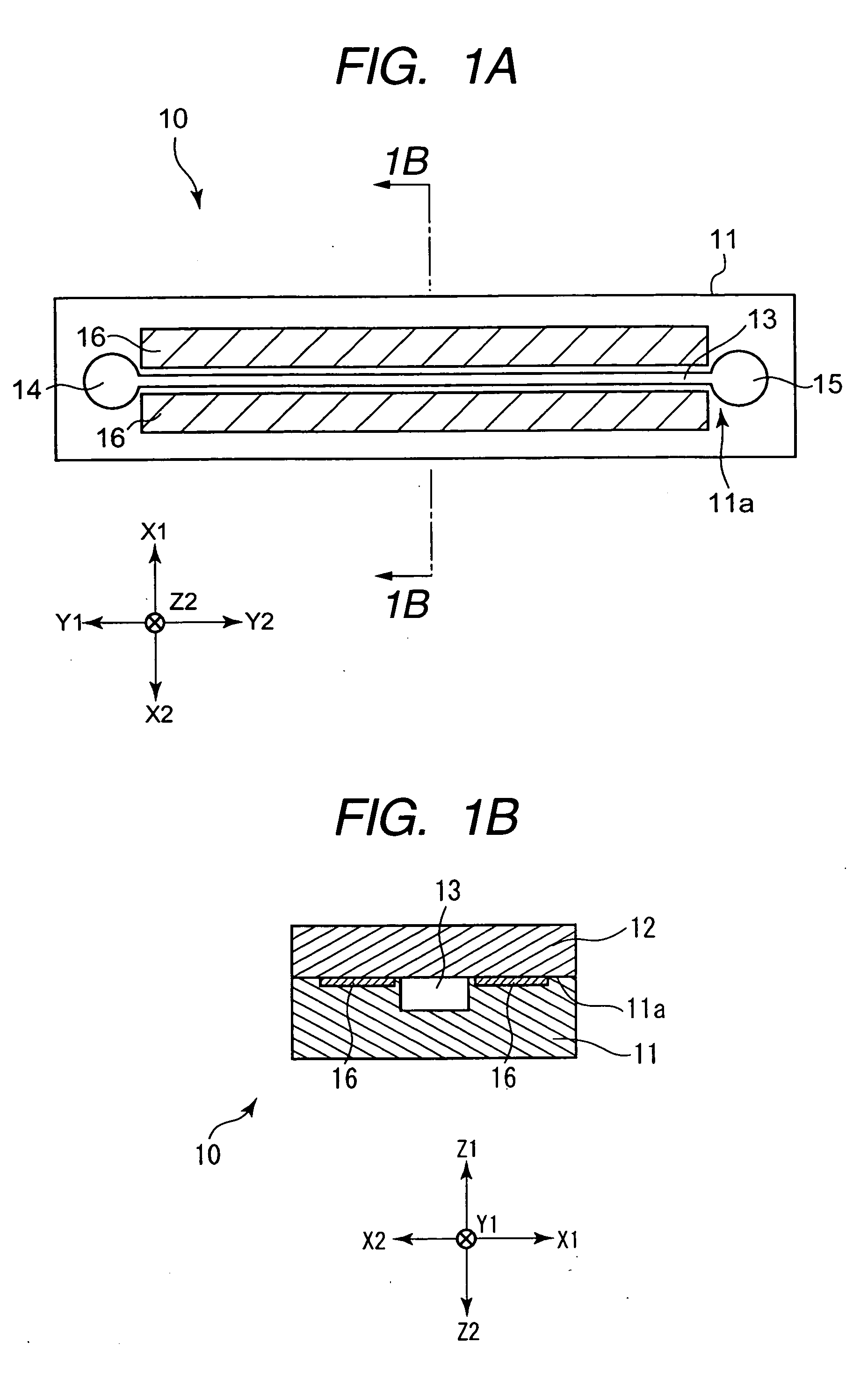
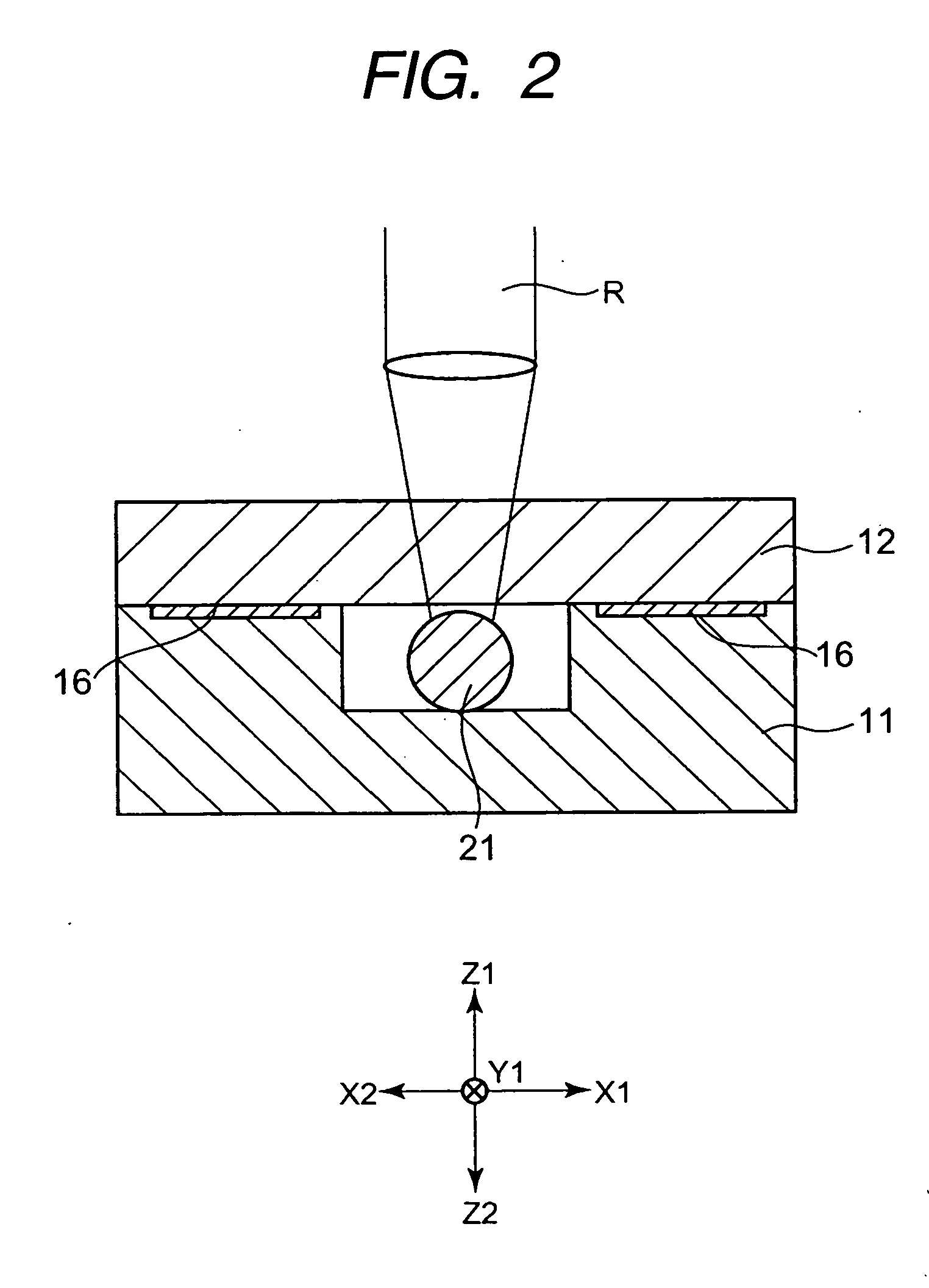
[0027]FIG. 1A is a plan view illustrating a testing plate of the present invention. FIG. 1B is a cross-sectional view taken along the line IB-IB of FIG. 1A. FIG. 2 is a diagram explaining a method of measuring a fluorescent intensity in the present invention. Moreover, in FIG. 1, oblique lines are shown so as to highlight light shielding portions.

[0028] A testing plate 10 shown in FIGS. 1A and 1B is a plate for performing a predetermined test where a test sample, such as blood collected from the human body, reacts to a predetermined reagent or the like. When the testing plate 10 is used as, for example, a DNA chip, the collected blood is subjected to a predetermined treatment so as to be used.

[0029] The testing plate 10 has a substantially rectangular-parallelepiped shape which has a predetermined thickness to extend in the longitudinal direction (Y1-Y2 direction in FIG. 1A) perpendicular to the width direction (X1-X2 direction in FIG. 1A). Moreover, the testing plate 10 may have ...


PUM

PropertyMeasurementUnit
Flow rateaaaaaaaaaa
Stabilityaaaaaaaaaa
Fluorescenceaaaaaaaaaa

Abstract

Light shielding portions are provided along a flow path on a top surface of a plate substrate at both sides, that is, an X1 side (right side) and an X2 side (left side) of the flow path. Then, when a fluorescent intensity is measured to determine whether a test sample reacts or not, a small amount of light emitted from the plate substrate and a lid body is also properly shielded by the light shielding portions, so that the stability of measuring the fluorescent intensity with respect to beads arranged inside the flow path can be improved.

Description

BACKGROUND OF THE INVENTION [0001] 1. Field of the Invention [0002] The present invention relates to a simple testing plate capable of performing, for example, a blood test and a DNA test by a medical institution or an individual, and more specifically, to a testing plate capable of more accurately performing fluorescence measurement for determining whether a biochemical reaction between probe DNA and sample DNA occurs or not. [0003] 2. Description of the Related Art [0004] Recently, a testing chip for testing a material collected from the human body, such as blood, has been increasingly developed. For example, a DNA chip where multiple kinds of DNA fragments (probes) are previously implanted in a substrate made of, for example, glass can measure expression of genes (test sample or target) collected from the human body at one time. [0005] Whether the test sample DNA reacts to the DNA fragments in the probe, for example, is determined by the following method. [0006] First, a test sam...

Claims


Application Information

Patent Timeline
IPC IPC(8): C12M1/34
CPCB01L3/5027B29C66/53461B01L2300/0636B01L2300/0645B01L2300/0887B01L2300/168B01L2300/1827B29C65/16B29C65/1696G01N21/0332G01N21/05G01N21/645G01N2201/064B29C65/1635B29C65/1674B29C65/1683G01N2021/0346B01L3/502707B29C66/1122B29C66/71B29C66/712B29C66/73921B29C66/8322B29K2033/12B29K2083/00
Inventor TAKAMURA, SHOZOYAMASHITA, TATSUMAROSHIBUYA, YOSHIHISA
Owner ALPS ALPINE CO LTD
Why Eureka
Try Eureka