Jointing sleeve component and joint electric wire

a technology of joint sleeve and electric wire, which is applied in the direction of coupling contact members, connection end caps, coupling device connections, etc., can solve the problems of high production cost, inability to obtain pipe materials having dimensions, and high material cost, so as to improve the reliability of crimping connections and reduce the cost of joint electric wires. , the effect of improving the production quality of joint electric wires

Active Publication Date: 2006-03-16
YAZAKI CORP
View PDF7 Cites 22 Cited by
  • Summary
  • Abstract
  • Description
  • Claims
  • Application Information

AI Technical Summary

Benefits of technology

[0011] It is therefore an objective of the present invention to solve the above problems and to provide a jointing sleeve component and a joint electric wire, by which the material cost can be reduced and the fluctuation in the crimping force can be reduced so as to improve in reliability of the crimp connection.
[0012] Another objective of the present invention to provide a jointing sleeve component and a joint electric wire, by which the positional relation between the sleeve and the electric wires can be fixed, the insulating coating is prevented from being caught or broken, and the quality stability and workability in connection of the joint electric wire can be improved.

Problems solved by technology

However, since a long pipe material is manufactured from a board material by consuming a lot of time and labor hour through many steps such as pressing, rolling and welding, therefore there is a problem that a material cost is high.
Further, since it is not easy to subject additional processing such as spreading and pressing to a pipe material, therefore there is a problem that a production cost is high.
Moreover, since dimensions of inner and outer diameters are determined to some extent, therefore there is a problem that it is not possible to obtain a pipe material having a dimension in accordance with a size of an electric wire.
In order to prevent the sleeve 41 from moving along the coated electric wire 43 during swaging, the sleeve 41 is crushed by using a crimping tool or the like so as to be provisionally crimped to the core wire ends 43b. However, when the sleeve 41 is crushed into a deformed shape, the property of the swaging is deteriorated, causing a problem that the sleeve 41 and the core wire ends 43b cannot be provisionally crimped to each other sufficiently firmly.
If the provisional crimping force is weak, the sleeve 41 might move during swaging, causing a problem that the insulating coating 43a is caught by the sleeve 41 moved causing breakage of the insulating coating 43b or deterioration in crimping force of a swaged part.
Moreover, when the sleeve 41 and the core wire ends 43b are provisionally crimped to each other, a jig for positioning or the like must be used in order to fix a positional relation between the sleeve41 and the core wire ends 43b, causing a problem that workability in connection of a joint electric wire is deteriorated.

Method used


Image

  • Jointing sleeve component and joint electric wire
  • Jointing sleeve component and joint electric wire
  • Jointing sleeve component and joint electric wire

Examples


Embodiment Construction

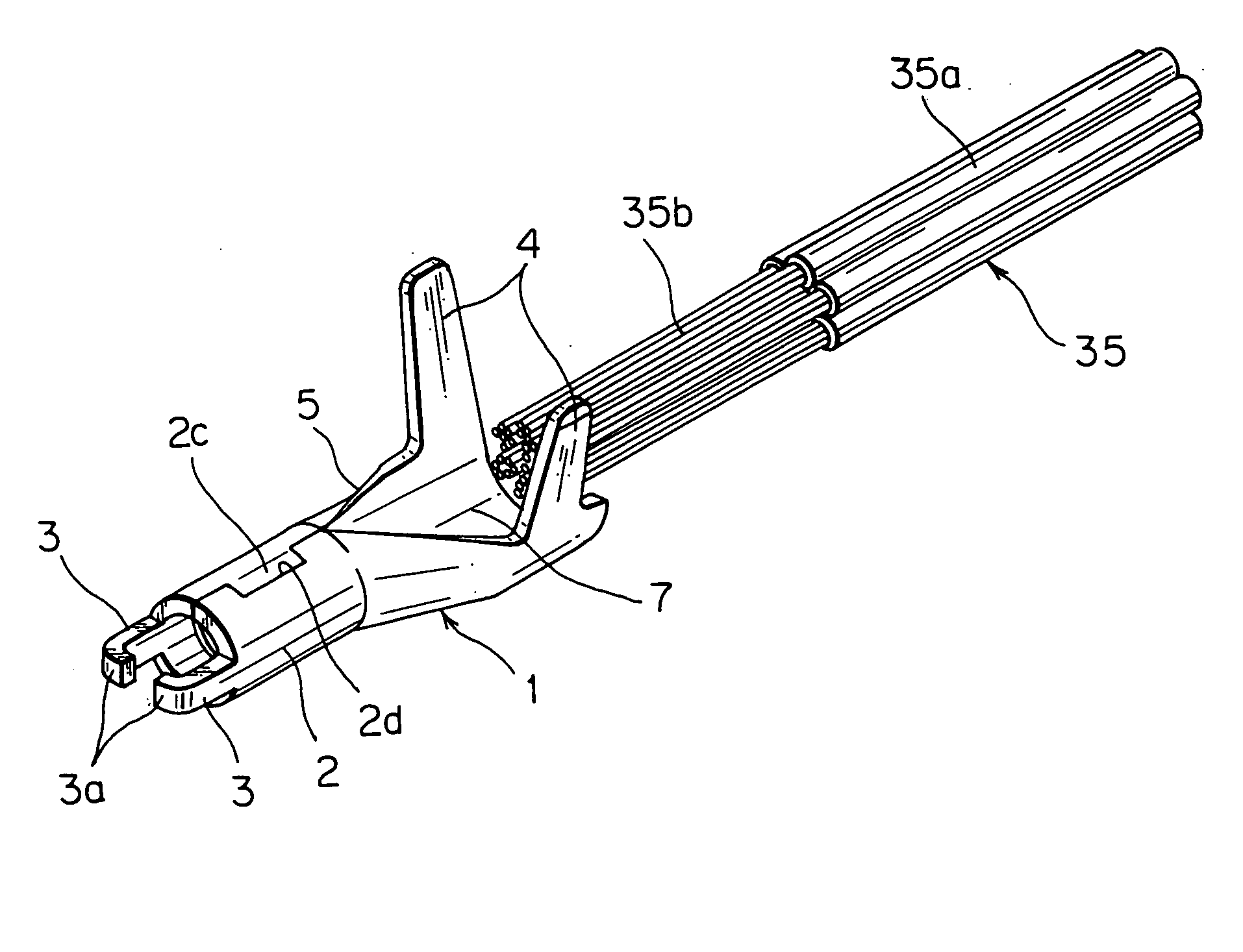
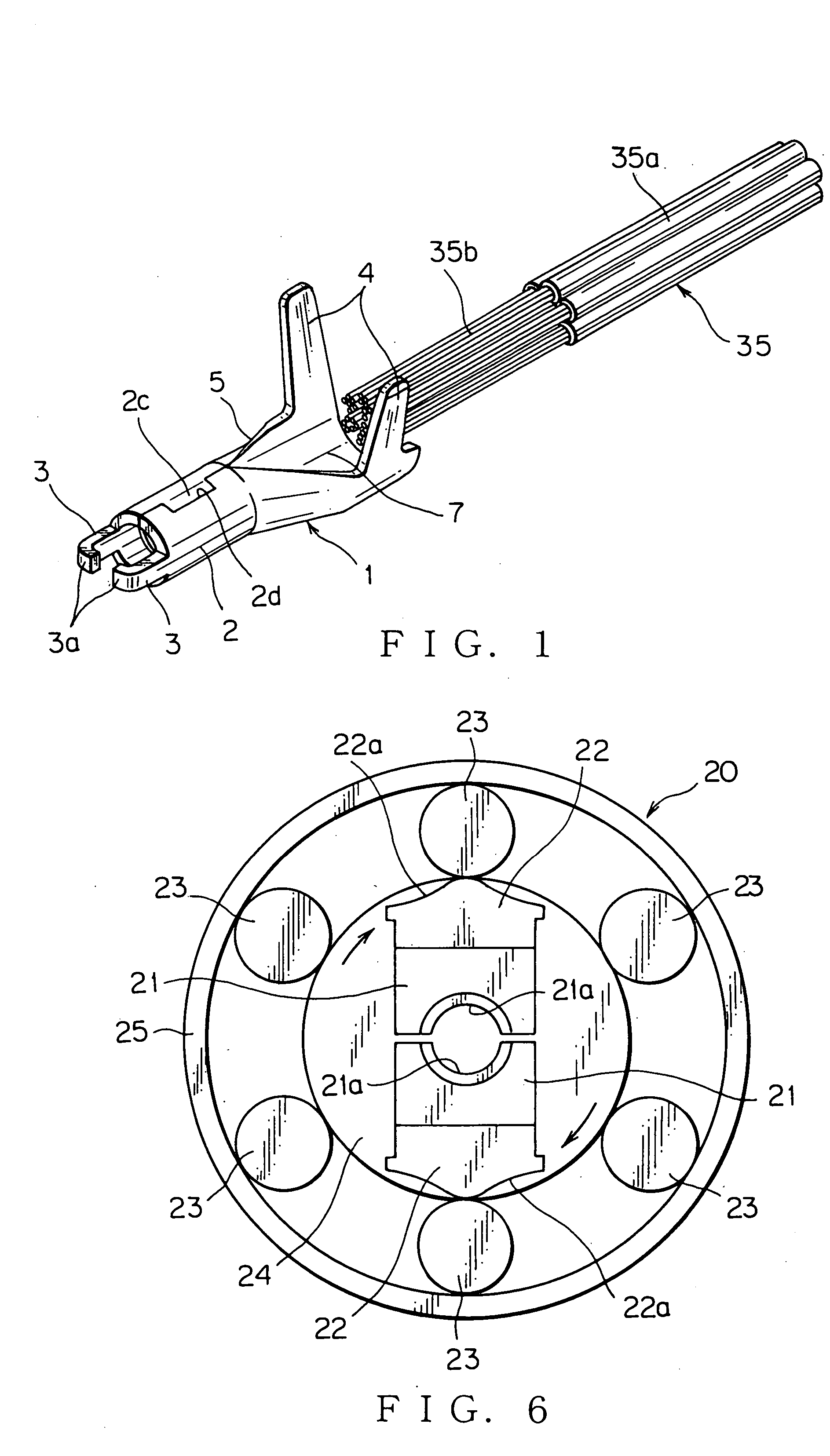
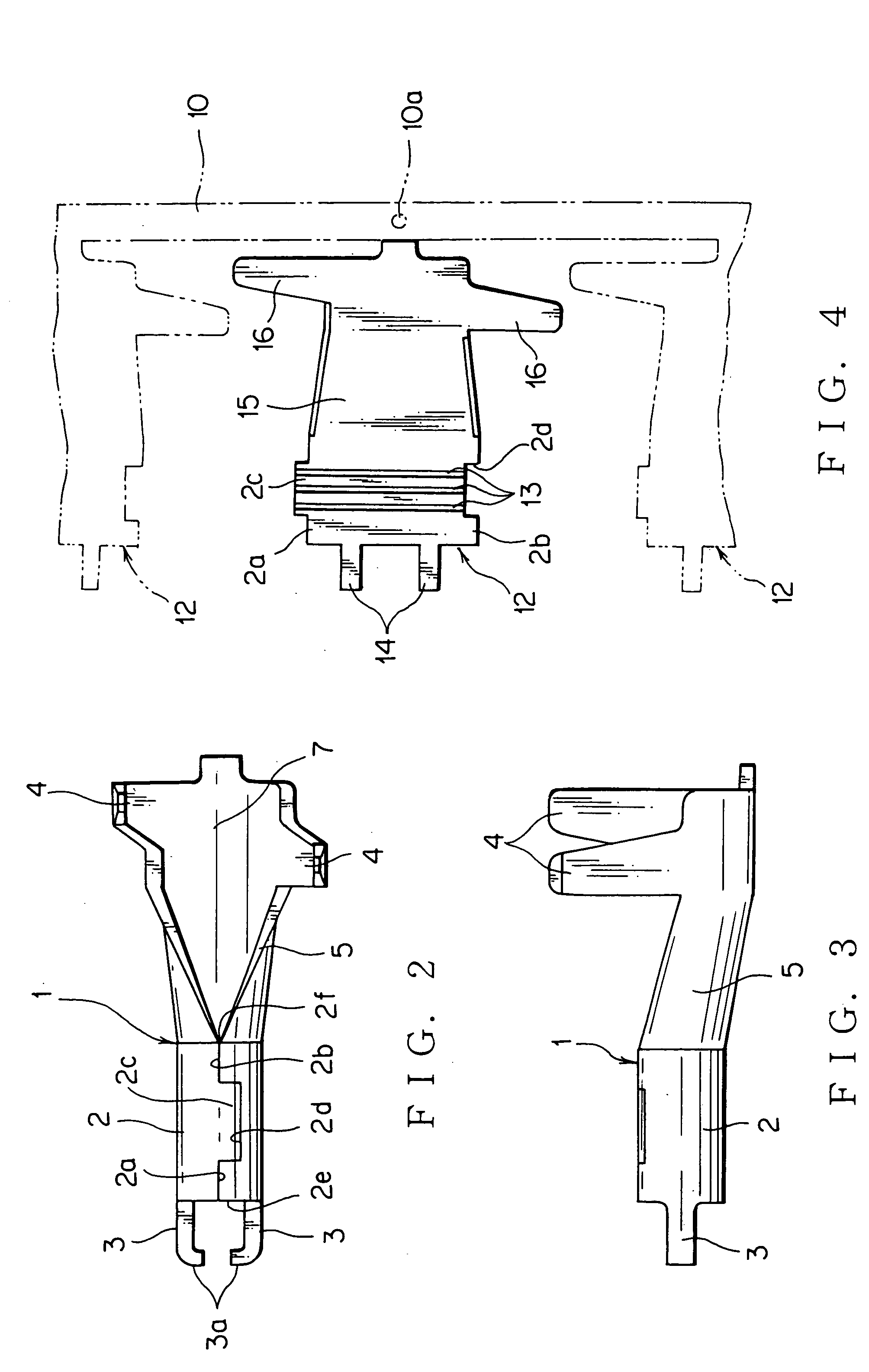
[0036] In the following, the preferred embodiments of the present invention will be explained with reference to the attached drawings. FIGS. 1-4 show a preferred embodiment of a jointing sleeve component of the present invention.

[0037] As shown in FIG. 1, the jointing sleeve component (hereinafter, sleeve component) 1 according to the preferred embodiment includes a sleeve (i.e. sleeve part) 2 formed by bending a developed material 12 (shown in FIG. 4) into a pipe-shape, wherein the developed material 12 is stamped out to have a specific shape from a plate made of electrically conductive metal such as copper, which has been plated.

[0038] Both ends of the pipe-shaped sleeve 2 are formed open so that core wire ends 35b, which are obtained by removing insulating coatings 35a from a plurality of coated electric wires 35, can be inserted into the sleeve 2. The sleeve 2 is reduced in its diameter by swaging, thereby electrically connecting the core wire ends 35b to each other. A joint e...


PUM


Abstract

The jointing sleeve component includes a sleeve made of electrically conductive metal. A diameter of the sleeve is to be reduced by swaging on a condition that core wire ends of a plurality of coated electric wires are received in the sleeve. Each core wire end is obtained by removing an insulating coating from the coated electric wire. The jointing sleeve component electrically connects the core wire ends to each other. The sleeve is formed in a pipe-shape from a developed material, which is stamped out from a plate made of the electrically conductive metal to have a specific shape.

Description

BACKGROUND OF THE INVENTION [0001] (1) Field of the Invention [0002] The present invention relates to a jointing sleeve component used for electrically connecting a plurality of core wire ends to each other, at each of which core wire end an insulating coating of a coated electric wire is removed, and a joint electric wire. [0003] (2) Description of the Related Art [0004] So far, when a joint electric wire has been formed, a pipe-shaped sleeve, both ends of which are formed open, has been used. As shown in FIGS. 7A and 7B, a long pipe material is cut into a specific length thereof and thereafter, subjected to plating, thereby the sleeve 41 is obtained. [0005] When core wire ends 43b are connected to each other by using the sleeve 41, the core wire ends 43b are inserted from one end 42a of the sleeve 41, then front ends of the core wire ends 43b are exposed from an opposite end 42b of the sleeve 41, then the sleeve 41 is subjected to provisional crimping by using a crimping tool such...

Claims


Application Information

Patent Timeline
Patent Type & Authority Applications(United States)
IPC IPC(8): H01R4/10
CPCH01R4/185Y10S439/948H01R43/048H01R4/22
Inventor SAKAGUCHI, TADAHISAONUMA, MASANORIASAKURA, NOBUYUKI
Owner YAZAKI CORP
Why Eureka
Try Eureka