Exhaust flap means

a technology of exhaust flap and means, which is applied in the direction of exhaust treatment, valve details, valve housings, etc., can solve the problems of shaft jamming in operation, damage to bearing means, and inexact coaxial passage openings opposite each other

Inactive Publication Date: 2006-03-23
PIERBURG GMBH & CO KG NEUSS
View PDF23 Cites 24 Cited by
  • Summary
  • Abstract
  • Description
  • Claims
  • Application Information

AI Technical Summary

Benefits of technology

[0005] It is the object of the invention to provide an exhaust flap means where the coaxiality differences can be evened out in a simple manner.

Problems solved by technology

With bulky engines in particular, it is known to switch off individual cylinders in certain driving situations to save fuel.
Because of manufacturing tolerances occurring, there exists the problem that the passage openings opposite each other are not exactly coaxial.
This may lead to a jamming of the shaft in operation or to damage to the bearing means.

Method used


Image

  • Exhaust flap means
  • Exhaust flap means
  • Exhaust flap means

Examples


Embodiment Construction

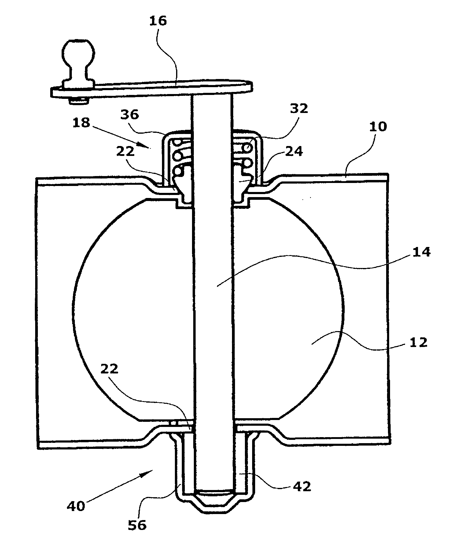
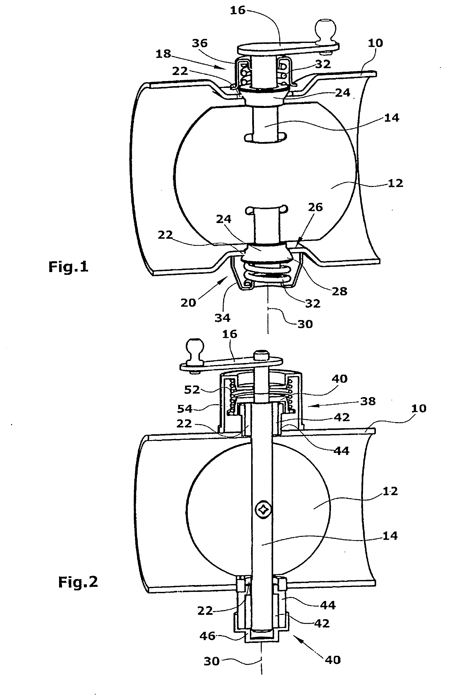
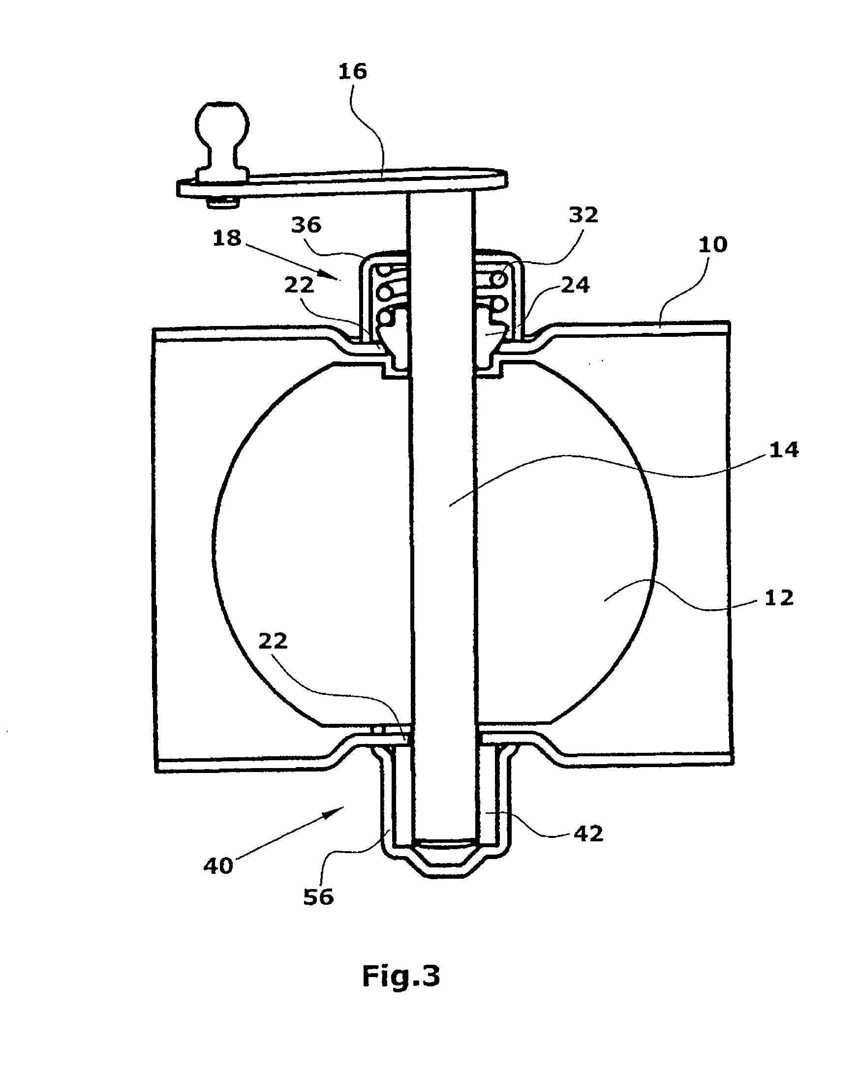
[0021] The exhaust flap means comprises a housing 10 which is substantially tubular and can be inserted into an exhaust gas train. Likewise, the housing 10 can be part of an exhaust pipe. In the housing 10, an exhaust flap 12 is arranged which is connected to a flap shaft 14. At one end, the flap shaft is connected with a lever mechanism 16 which, in turn, is connected with a non-illustrated setting means in an electric motor via a rod assembly or the like. By actuating the setting means, the exhaust flap 12 can be pivoted from the illustrated open position into the closed position that is rotated by 90° at maximum. It goes without saying that intermediate positions are possible as well.

[0022] The flap shaft 14 is supported in two bearing means 18,20 opposite each other. To this end, the housing 10 comprises two passage openings 22 opposite each other which should be arranged coaxially to each other, if possible. Since a coaxiality of the two passage openings 22 is not always given...


PUM


Abstract

An exhaust flap means for motor vehicles comprises a housing (10) in which an exhaust flap (12) is arranged. The exhaust flap (12) is connected with a flap shaft (14) for pivoting the exhaust flap (12). The housing (10) comprises two passage openings (22) opposite each other for guiding through the flap shaft (14). Further, two bearing means (18,40) for supporting the flap shaft (14) are provided. To permit an evening out of an offset between the two passage openings (22), one bearing means (18) comprises a bearing body (24) of ceramics, which has a spherical configuration. The opposite bearing means (40) comprises a bearing sleeve of graphite.

Description

[0001] The present application claims priority to German Patent Application No. 10 2004 046 077.9, filed Sep. 23, 2004, which application is incorporated herein fully by this reference. BACKGROUND OF THE INVENTION [0002] The invention relates to an exhaust flap means. [0003] With bulky engines in particular, it is known to switch off individual cylinders in certain driving situations to save fuel. To further maintain the required counterpressure in the exhaust gas train, exhaust flaps are provided in individual exhaust pipes. Further, the provision of exhaust flaps serves the purpose of keeping the engine noise unchanged, if possible, even if some of the cylinders are switched off. [0004] The exhaust flap means for motor vehicles comprises a housing in which the exhaust flap is arranged. The particularly tubular housing is inserted into the exhaust gas train. Likewise, the housing can be part of the exhaust gas train. The exhaust flap is pivotably supported in the housing via a flap...

Claims


Application Information

Patent Timeline
Patent Type & Authority Applications(United States)
IPC IPC(8): F01N7/00
CPCF01N2260/14F16K27/0218F02D9/106F02D9/04
Inventor GERARDS, HANSWAGNER, TOBIASCHASSEE, STEPHANRAUSCHNING, UDO
Owner PIERBURG GMBH & CO KG NEUSS
Why Eureka
Try Eureka