
Carbonator with remote liquid level sensor

a technology of liquid level sensor and carbonator, which is applied in the direction of combustible gas purification/modification, heating type, separation process, etc., can solve the problems of increasing ice usage, affecting the performance of beverage dispensers, and affecting the use of beverage dispensers, and occupying a large space inside the dispenser housing for convenient and accessible mounting of carbonators

Inactive Publication Date: 2006-03-23
JABLONSKI THADDEUS M +1
View PDF11 Cites 2 Cited by
  • Summary
  • Abstract
  • Description
  • Claims
  • Application Information

AI Technical Summary

Benefits of technology

[0009] In a preferred embodiment, the carbonator also includes pressure relief means located remote from the carbonator tank and means for fluid coupling the pressure relief means to interior of the tank for relieving overpressure in the tank. The means for fluid coupling the pressure relief means may include the means for fluid coupling the liquid level sensing means to the tank interior, and the carbonator can advantageously have first fluid conduit means having an inlet remote from the tank for fluid coupling to a source of liquid and an outlet fluid coupled to the tank liquid inlet; second fluid conduit means having an inlet remote from the tank for fluid coupling to a source of carbonating gas and an outlet fluid coupled to the tank carbonating gas inlet; and third fluid conduit means having an inlet coupled to the tank carbonated liquid outlet and an outlet remote from the tank for fluid coupling to a point of use of carbonated liquid. In addition, the carbonator can include means responsive to the liquid level sensing means sensing less than a predetermined level of liquid in the carbonator tank for delivering liquid to the tank liquid inlet. The means responsive may comprise pump means fluid coupled between a supply of liquid and the tank liquid inlet, and control means coupled to the liquid level sensing means and to the pump means for operating the pump means to deliver liquid to the tank liquid inlet in responsive to a sensed level of liquid in the tank being less than the predetermined level.
[0010] The invention also contemplates a beverage dispensing apparatus that embodies such a carbonator. In this case, the beverage dispensing apparatus comprises a housing; a beverage dispensing valve carried by the housing; a carbonator including a carbonator tank positioned at a first location in the housing, the tank having a liquid inlet, a carbonating gas inlet and a carbonated liquid outlet; liquid level sensing means positioned at a second location in the housing remote from both the first location and from the carbonator tank; means for fluid coupling the liquid level sensing means to an interior of the tank for sensing the level of liquid in the tank; means responsive to the liquid level sensing means sensing less than a predetermined level of liquid in the tank for delivering liquid to the tank liquid inlet; and means for fluid coupling the tank carbonated liquid outlet to the beverage valve to deliver carbonated liquid to the valve.

Problems solved by technology

A problem with beverage dispensers that use carbonators concerns placement of the carbonator within the dispenser.
Locating the carbonator to the exterior of a dispenser is known, but ambient warming of the carbonator and its contents then becomes a problem in terms of dispenser performance and increased ice usage, since the cold plate is then required to chill carbonated water that is warmer than would be the case if the carbonator were located within the dispenser.
However, a difficulty that arises is in choosing the particular location for the carbonator, since the liquid level sensor inside of the carbonator tank and the pressure relief safety valve on the tank are serviceable parts that can and do malfunction and require periodic replacement.
If the carbonator is placed in a relatively inaccessible location within the dispenser housing, should the liquid level sensor and / or pressure relief safety valve fail or require periodic replacement or maintenance, considerable disassembly of the beverage dispenser, at considerable cost, can be required to access and service the carbonator for repair or replacement of its components.
Unfortunately, as ice / beverage dispensers evolve to offer more and more features and performance advantages to users, the space available inside of dispenser housings for convenient and accessible mounting of carbonators has become ever more scarce, often leaving no choice but to mount the carbonator within the dispenser housing at a location that makes it relatively inaccessible and difficult to reach for service or repair of its liquid level sensor and pressure relief valve.

Method used


Image

  • Carbonator with remote liquid level sensor
  • Carbonator with remote liquid level sensor
  • Carbonator with remote liquid level sensor

Examples


Embodiment Construction

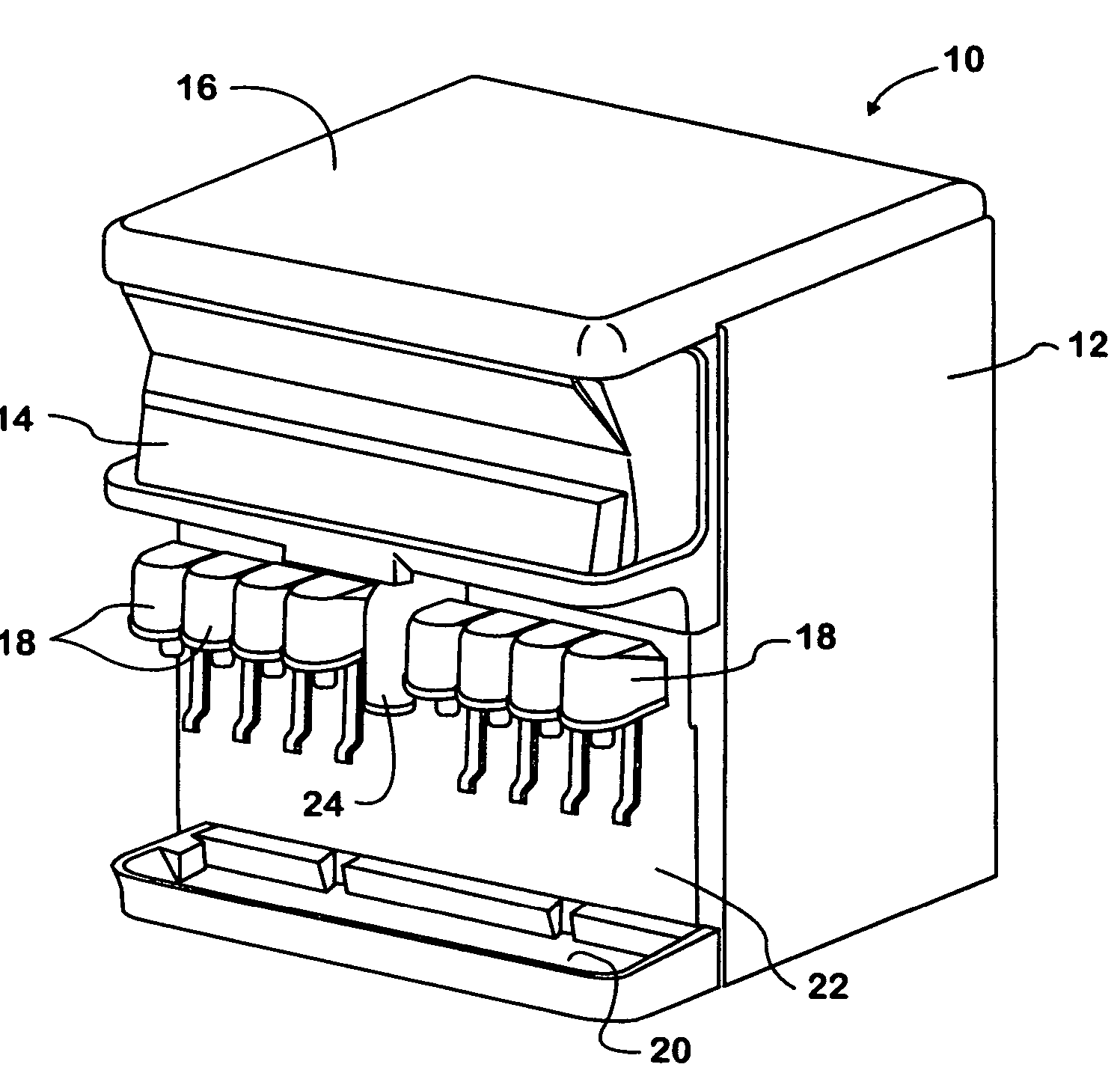
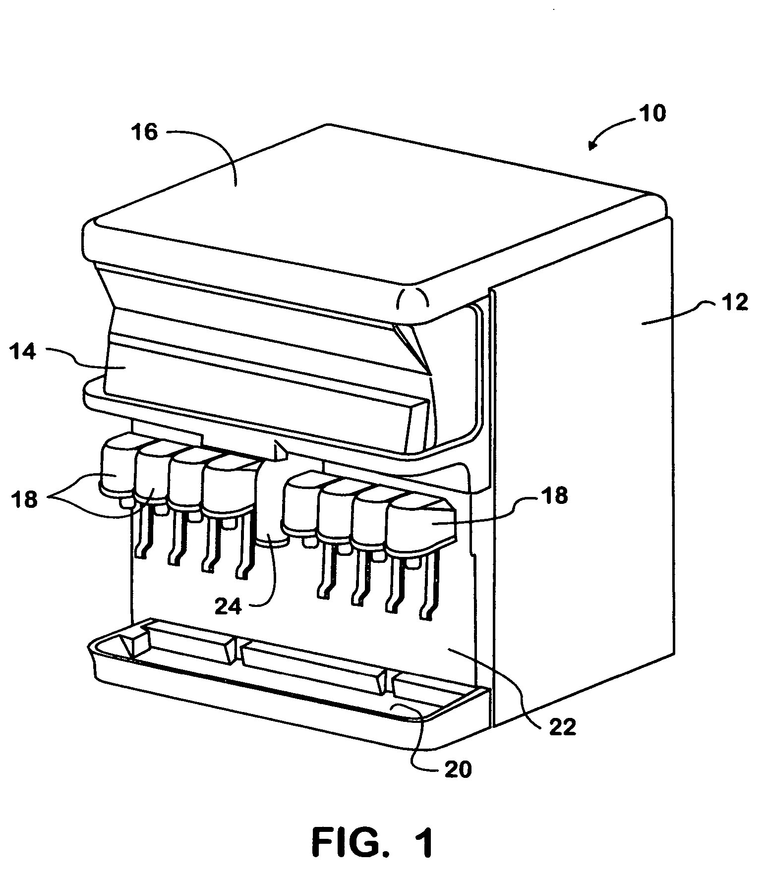
[0021] The present invention may advantageously be incorporated into a combined ice and beverage dispensing machine of a general type as seen in FIG. 1 and indicated generally at 10. As is customary, the dispenser includes an outer housing 12, a merchandising cover 14 and a removable ice bin cover 16. A plurality of beverage dispensing valves 18 is secured to a front surface of the dispenser above a drip tray 20 and adjacent a splash panel 22. An ice dispensing chute 24 is secured to the front surface of the dispenser centrally of the valves 18 and above the drip tray 20.

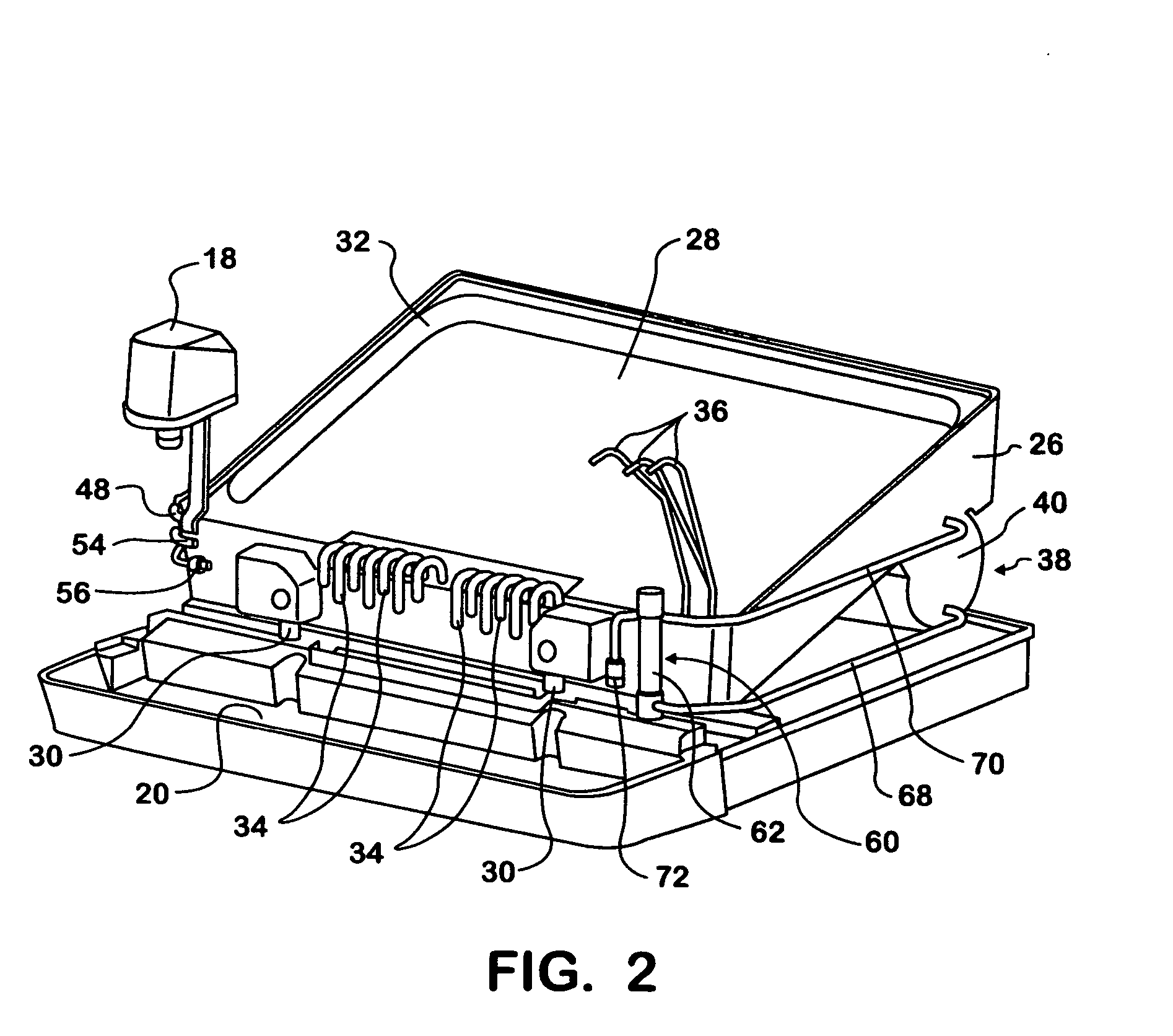
[0022] As seen in FIG. 2, a cold plate 26 is placed within and toward a lower end of the ice / beverage dispenser housing 12. Although not shown, it is understood that an ice retaining bin or hopper is contained within an upper portion of the housing above the cold plate and that the bin has a forward ice outlet opening through which ice to be dispensed exits the bin for flow into, through and out of the ice dispensi...


PUM

PropertyMeasurementUnit
liquid levelaaaaaaaaaa
pressure reliefaaaaaaaaaa
pressureaaaaaaaaaa

Abstract

A carbonator for a beverage dispenser is characterized by a carbonator tank that is placed at a generally inaccessible first location in the beverage dispenser. Liquid and CO2 are supplied to the tank to carbonate liquid in the tank and carbonated liquid at an outlet from the tank is delivered to a beverage dispensing valve. To control delivery of liquid to the carbonator tank and thereby the level of liquid in the tank, a liquid level sensor is fluid coupled to an interior of the tank and is placed in the beverage dispenser at a generally accessible second location that is remote from the first location and from the tank. Placement of the liquid level sensor remote from the carbonator tank and at an accessible location facilitates its repair and replacement.

Description

[0001] This application claims benefit of provisional patent application Ser. No. 60 / 611,724, filed Sep. 21, 2004.FIELD OF THE INVENTION [0002] The present invention relates generally to beverage dispensers and in particular to carbonators for beverage dispensers. BACKGROUND OF THE INVENTION [0003] It is known in the beverage dispensing art to use cold plates to provide heat exchange cooling of drinks. The cold plate itself is cooled by a volume of ice placed in contact with it and, in turn, provides for cooling of beverage liquids flowed through circuits or tubes embedded in the cold plate. A cold plate often is used in conjunction with a post-mix beverage dispenser, in which case sources of plain and carbonated water and beverage syrup flavorings are connected to the cold plate to be cooled as they are passed through the cold plate circuits. A carbonated or non-carbonated drink is then produced when the cooled carbonated or plain water and syrup flavoring constituents are subseque...

Claims


Application Information

Patent Timeline
Patent Type & Authority Applications(United States)
IPC IPC(8): B67D5/56B67D7/74
CPCB67D1/0871B67D1/0057Y10S261/07
Inventor JABLONSKI, THADDEUS M.TOBLER, ANDREW J.
Owner JABLONSKI THADDEUS M
Learn More