Rubber injection molding device and rubber product manufacturing method

a technology of which is applied in the field of rubber injection molding device and rubber product manufacturing method, can solve the problems of less manufacturing efficiency, a large number of molds, and short vulcanization time in injection molding of rubber products using rubber injection molding device, so as to reduce the vulcanization time and eliminate various problems, the effect of reducing the occurrence of residual rubber

Inactive Publication Date: 2006-03-23
SUMITOMO RIKO CO LTD +1
View PDF12 Cites 10 Cited by
  • Summary
  • Abstract
  • Description
  • Claims
  • Application Information

AI Technical Summary

Benefits of technology

[0046] Next, in the eight mode, not only does the injection chamber have a shape that narrows in the tip part until it reaches the nozzle at the tip end of the injection cylinder, but also the tip part of the injection plunger, corresponding thereto has a shape that narrows with the same shape as the tip part of the injection chamber. Therefore, at the forward limit, they mate together, structured so that the tip end of the injection chamber is filled with the tip end of the injection plunger, and thus, it is possible to eliminate the occurrence of residual rubber within the injection cylinder after the injection. Having the structure that is combined with the prevention of the occurrence of residual rubber within the feed duct in the first mode, this causes the rubber that is pushed from the feed machine to be completely replaced, without fail, with each injection cycle, with none remaining, making it possible to have the rubber temperature for the entire rubber injection molding device be high, allowing the rubber temperature of the injection rubber to be even higher, making it possible to reduce substantially the vulcanization time.
[0047] The ninth mode relates to method of manufacturing rubber products, where, when performing injection molding of rubber products using an injection molding device, the rubber remaining within the feed duct after the feed operation of the rubber by the feed machine is pushed into the injection chamber by a pushing assembly, and, thereafter, the forward motion of the injection plunger causes the rubber within the injection chamber to be injected into the molding cavity, and vulcaniztion is performed. With this method of manufacturing, the remaining rubber within the feed duct can be eliminated, making it possible to eliminate various problems caused by supplying into the injection chamber scorched rubber or rubber with non-uniform temperature. Furthermore, by eliminating the residual rubber within the feed duct, the temperature of the rubber that is supplied into the molding cavity, and the setting for the temperature of the rubber in the rubber injection molding device can be increased, thus enabling the vulcanization time to be reduced effectively and substantially.

Problems solved by technology

Conventionally, to make the vulcanization time short in injection molding of rubber products using rubber injection molding devices has been a major issue.
The longer the vulcanization time, the less the manufacturing efficiency, which not only requires a greater number of molds, but also increases the amount of space occupied by the vulcanization equipment commensurately.
However, in conventional rubber injection molding devices, when, as shown in FIG. 9B, the rubber within the injection chamber 210 is injected by the forward motion of the injection plunger 212, there will be residual rubber within the straight injection duct 218 and within the feed duct 228, which connects between the feed aperture 226 at the tip of the feed cylinder 220 and the injection chamber 210, and thus if the set temperature for the injection chamber 210 is increased too far, then scorching (burning of the rubber) will result Because scorched rubber has an adverse effect on product quality, the problem cannot be solved by simply increasing the set temperature.
However, in these conventional devices, no consideration has been given to the rubber that remains in the feed duct 228.
If, in order to prevent this reduction in temperature, heating apparatus are provided around the periphery of the feed duct, then scorching will become a problem.
Conventionally, these problems have not been addressed, nor have any means of resolution thereof been disclosed or proposed.

Method used


Image

  • Rubber injection molding device and rubber product manufacturing method
  • Rubber injection molding device and rubber product manufacturing method
  • Rubber injection molding device and rubber product manufacturing method

Examples


Embodiment Construction

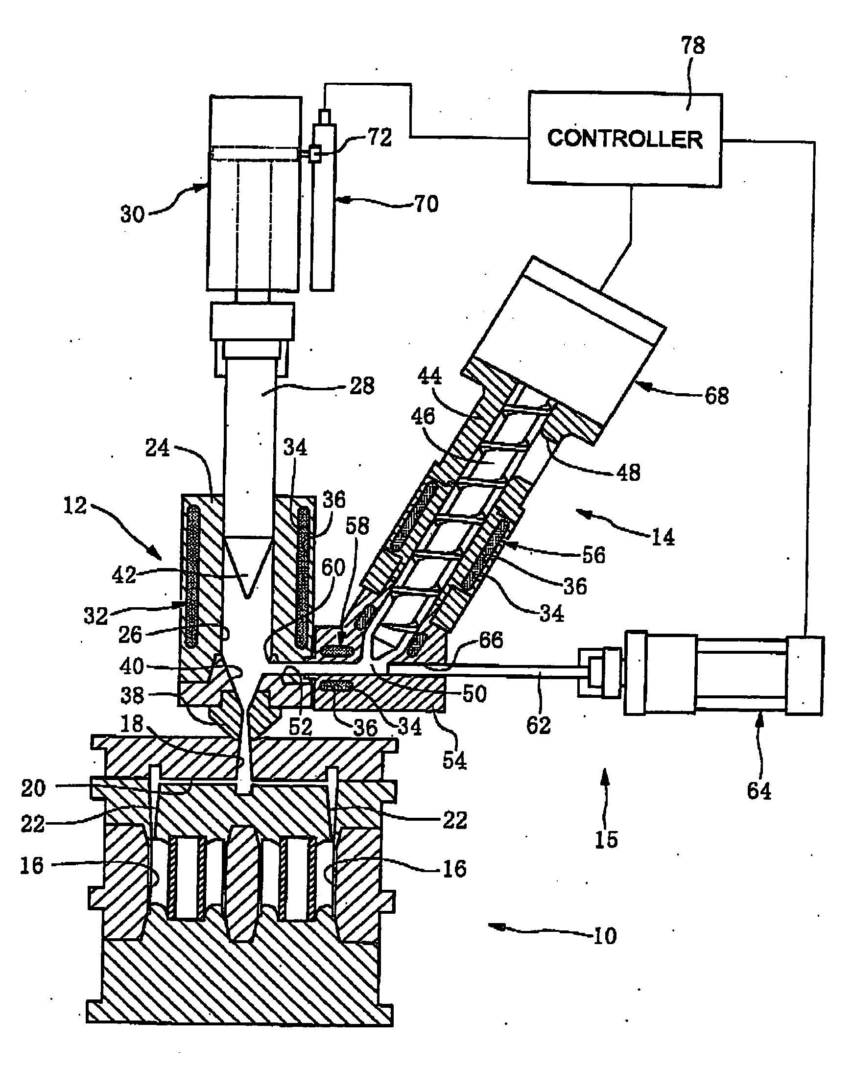
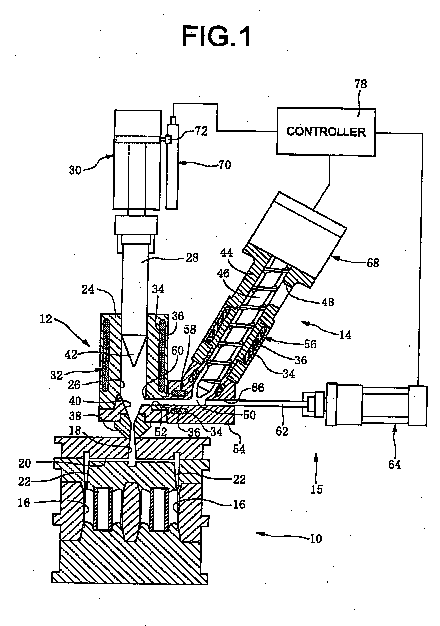
[0058]FIG. 1 illustrates the overall structure of a rubber injection molding device according to a form of embodiment of the present invention. As is shown in FIG. 1, the rubber injection molding device is equipped with a pushing assembly 15 in addition to a mold 10, and injecting machine 12 and a feed machine 14.

[0059] The mold 10 has a molding cavity 16 therein, and also has a sprue 18, a runner 20, and a gate 22, connected to this molding cavity 16. 24 is an injection cylinder of the injecting machine 12. The injection cylinder 24 includes an injection chamber 26. A rubber is charged into this injection chamber 26, and then is expelled from a nozzle 38 at the tip part of the injection cylinder 24 (the bottom tip, as shown in the figure) by the forward motion of an injection plunger 28, shown as motion in the downward direction in FIG. 1, and is injected into the molding cavity 16 of the mold 10.

[0060] The injection plunger 28 is driven in the forward direction, which is the dow...


PUM

PropertyMeasurementUnit
temperatureaaaaaaaaaa

Abstract

A rubber injection molding device comprising: a mold hang a molding cavity therein; an injecting machine including an injection cylinder having an injection chamber for storing a rubber therein, and an injection plunger for injecting the rubber from the injection chamber into the molding cavity by means of an advancement of the injection plunger; a feed machine having a feed cylinder with a feed aperture formed at a tip end thereof and connected with the injection chamber through a feed duct, and being adapted to feed into the injection chamber, through the feed duct the rubber in a mixed state, and a pushing assembly which pushes into the injection chamber the rubber that remains within the feed duct after a feed operation of the rubber by the feed machine. A manufacturing method of a rubber product by using the molding device is also disclosed.

Description

INCORPORATED BY REFERENCE [0001] The disclosure of Japanese Patent Application No. 2004-267452 filed on Sep. 14, 2004 including the specification, drawings and abstract is incorporated herein by reference in its entirety. BACKGROUND OF THE INVENTION [0002] 1. Field of the Invention [0003] The present invention relates to rubber injection molding devices and rubber product manufacturing methods using injection molding. [0004] 2. Description of the Related Art [0005] Conventionally, the injection molding method has been used broadly as a rubber product molding method. FIG. 8 shows an example of that which has been used conventionally as a rubber injection molding device. In this figure, 200 denotes an injection mold that has a molding cavity 202. 204 denotes an injecting machine, and 206 denotes a feed machine. The injecting machine 204 has an injection chamber 210 in an injection cylinder 208, where the rubber, which is charged to a set charge amount, in this injection chamber 210 an...

Claims


Application Information

Patent Timeline
Patent Type & Authority Applications(United States)
IPC IPC(8): B29C45/00
CPCB29K2021/00B29C45/54Y02W30/62
Inventor INUKAI, YUKIOKATO, SHIGEKIAOI, TAKAHIROKIMURA, NORIHITOIMAI, TAKAHIROAKATSUKA, YUKIONO, MASAMI
Owner SUMITOMO RIKO CO LTD
Why Eureka
Try Eureka