Rear vehicle body structure

a rear vehicle and body technology, applied in the direction of roofs, vehicle arrangements, transportation and packaging, etc., can solve the problems of inability to perform uniform absorption of load in the side member, inability to increase rigidity in simple ways, and inability to perform uniform absorption of load, so as to achieve efficient loading of springs and efficient load absorbing

Inactive Publication Date: 2006-03-23
SUZUKI MOTOR CORP
View PDF8 Cites 35 Cited by
  • Summary
  • Abstract
  • Description
  • Claims
  • Application Information

AI Technical Summary

Benefits of technology

[0012] According to the rear vehicle body structure in accordance with the present invention, a uniform

Problems solved by technology

On the other hand, in the case where a load from the rear is absorbed, if there is an extreme difference in rigidity of side member depending on placees, namely, locally, there arises a problem in that the absorption of load in the side member does not proceed uniformly.
However, in this case as well, since there is produced a difference in rigidity of side member depending on places, the rigidity cannot be increased in simple way.
However, with the conve

Method used


Image

  • Rear vehicle body structure
  • Rear vehicle body structure
  • Rear vehicle body structure

Examples


Embodiment Construction

[0021] An embodiment of the present invention will now be described in detail with reference to the accompanying drawings.

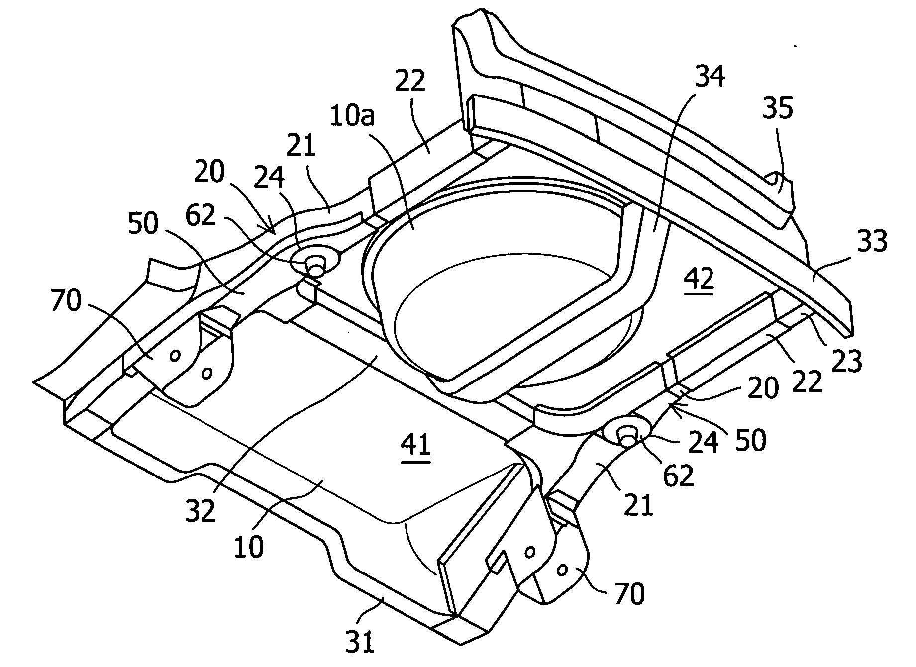
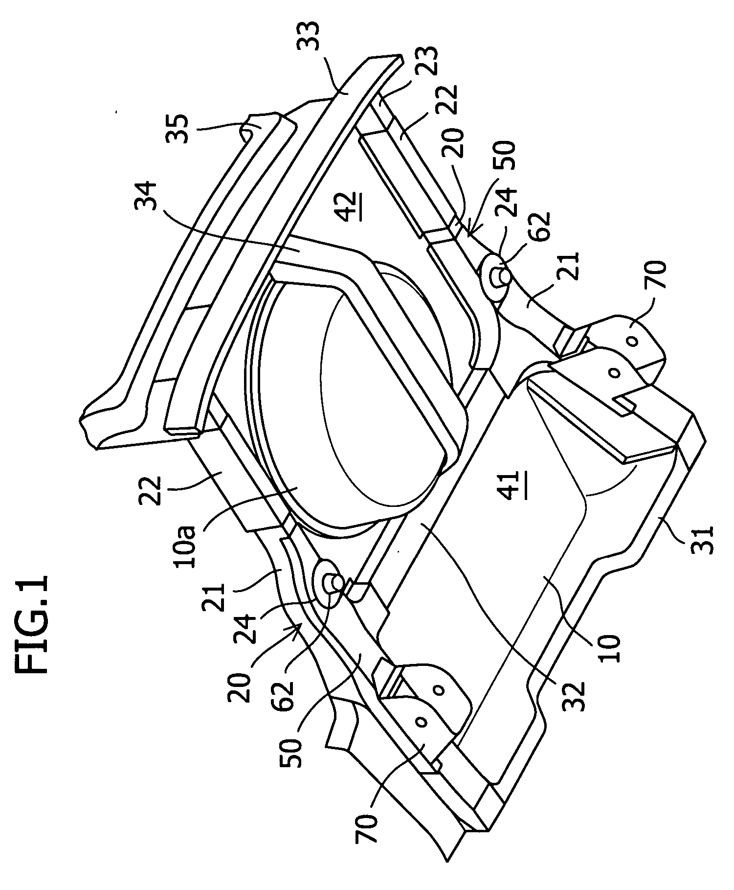
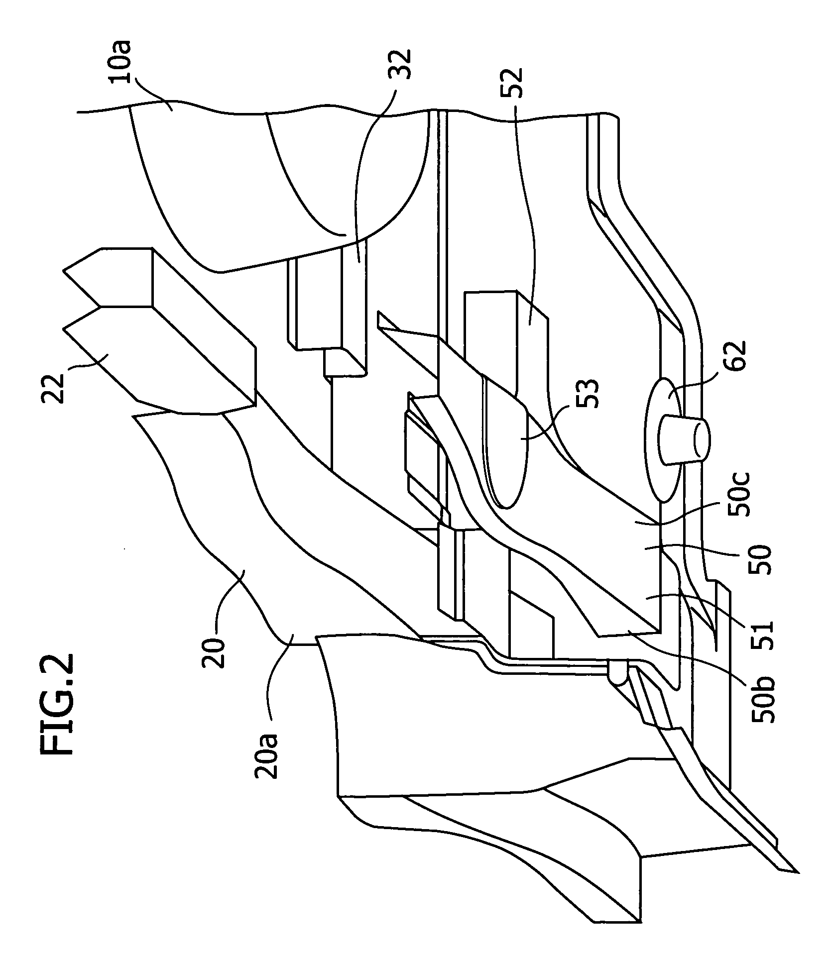
[0022]FIG. 1 is a perspective view of a rear vehicle body, viewed from the downside in the rear of a vehicle body, FIG. 2 is a partially enlarged broken perspective view of FIG. 1, FIG. 3 is a partially enlarged perspective view of FIG. 1, FIG. 4 is a perspective view showing a seat surface portion of a suspension spring shown in FIG. 1, FIG. 5 is a bottom view showing a rear vehicle body structure shown in FIG. 3, FIG. 6 is a bottom view enlargedly showing a reinforcing panel shown in FIG. 5, and FIG. 7 is a perspective view of the reinforcing panel shown in FIG. 6.

[0023] In FIGS. 1 to 3, reference numeral 10 denotes a rear floor panel forming a floor of a rear vehicle body, and on the rear side thereof, a spare tire housing 10a for housing a spare tire is provided. Reference numeral 20 denotes a pair of right and left rear side members disposed in the vehicle...


PUM


Abstract

It is an object of the present invention to increase the rigidity of a seat surface portion, to which a seat for a suspension spring is attached, of a rear side member in a vehicle body rear part. The present invention is characterized by a rear vehicle body structure in which at least intermediate portions of a pair of right and left rear side members are connected to each other by a cross member, and the seat surface portion for the suspension spring is provided on the rear side member, wherein a reinforcing panel for connecting the rear side member to the cross member is provided in a connecting portion between the rear side member and the cross member; the rear end position of the reinforcing panel is set at a substantially middle position between the connecting portion between the rear side member and the cross member and the rear end of the rear side member; and the seat surface portion for the suspension spring is set at a substantially middle position between the connecting portion between the rear side member and the cross member and the rear end of the reinforcing panel.

Description

FIELD OF THE INVENTION AND RELATED ART STATEMENT [0001] The present invention relates to a rear vehicle body structure capable of increasing the rigidity of a seat surface portion, to which a seat for a suspension spring is attached, of a rear side member in a vehicle body rear part. [0002] Conventionally, on the rear side of a vehicle body, a pair of right and left rear side members for supporting the lower surface side of a rear floor panel, and a member for connecting these rear side members to each other and a cross member are provided. A portion in which the rear side member and the cross member are connected to each other requires a sufficient connecting rigidity to greatly contribute to the rigidity of the vehicle body. [0003] On the other hand, in the case where a load from the rear is absorbed, if there is an extreme difference in rigidity of side member depending on placees, namely, locally, there arises a problem in that the absorption of load in the side member does not ...

Claims


Application Information

Patent Timeline
IPC IPC(8): B62D25/08
CPCB62D25/087B62D25/2027B62D25/088
Inventor KOBAYASHI, AKIRATSUKAKOSHI, TAKANORI
Owner SUZUKI MOTOR CORP
Why Eureka
Try Eureka