
Receptacle locator

a receptacle and locator technology, applied in the field of repositionable receptacles, can solve the problems of increasing labor and expense, increasing time and effort, and increasing the number of inefficiencies, and achieve the effect of quick and accurate positioning of receptacles

Inactive Publication Date: 2006-03-23
CONTINENTAL COMML PRODS
View PDF76 Cites 24 Cited by
  • Summary
  • Abstract
  • Description
  • Claims
  • Application Information

AI Technical Summary

Benefits of technology

[0006] It is in view of the above problems that the present invention was developed. The invention includes methods and apparatus for quickly and accurately positioning a receptacle at a positive location at which the user desires to handle the receptacle.
[0007] In a first preferred embodiment a system is provided for accurately positioning a receptacle at a positive location. The system includes a small inexpensive radio frequency tag or transponder in place at a location (preferably in an enclosure located below grade) where the receptacle is to be located. The receptacle has a sensor that beeps or blinks to indicate whether the receptacle is at the positive location. The vehicle, with the articulating arms used to empty the receptacle, would also have a sensor so that emptying of the receptacle could be recorded for billing purposes. In another preferred embodiment, the receptacle has a sensor, a power source (e.g. a battery), an indicator (e.g. a beep sequence or a needle gauge), and a memory storage device.
[0009] Additionally, the transceiver may be part of an RFID tag reader located on the receptacle. A computerized memory storage device may be on the receptacle for storing tracking information regarding the receptacle. Further, the memory may communicate the tracking information to the transceiver. The receptacle may also include a motion sensor communicating with the indicator such that the indicator only indicates whether the receptacle is at the pre-selected location of the tag when the receptacle is moving. Preferably, a timer also communicates with the indicator to turn off the indicator a pre-selected time after the receptacle stops moving. Both the motion sensor and timer serve to reduce power consumption of the components located on the receptacle thereby extending battery life for battery operated embodiments.

Problems solved by technology

Since the receptacles are movable, the truck operator frequently finds the receptacles out of the proper lifting position.
A task that should have taken no more than half a minute may therefore take much more time and effort, resulting in an increase in the labor and expense associated with performing the task.
If the misalignment occurs at a high percentage of the truck operator's stops, the resulting inefficiencies multiply rapidly.
Worse still, in situations where the receptacle is employed in an automated, or semi-automated environment (e.g. the receptacle is a source of raw materials feeding an automated line), the misalignment may result in waste, spillage, or a shortage of the feed product.

Method used


Image

  • Receptacle locator
  • Receptacle locator
  • Receptacle locator

Examples


Embodiment Construction

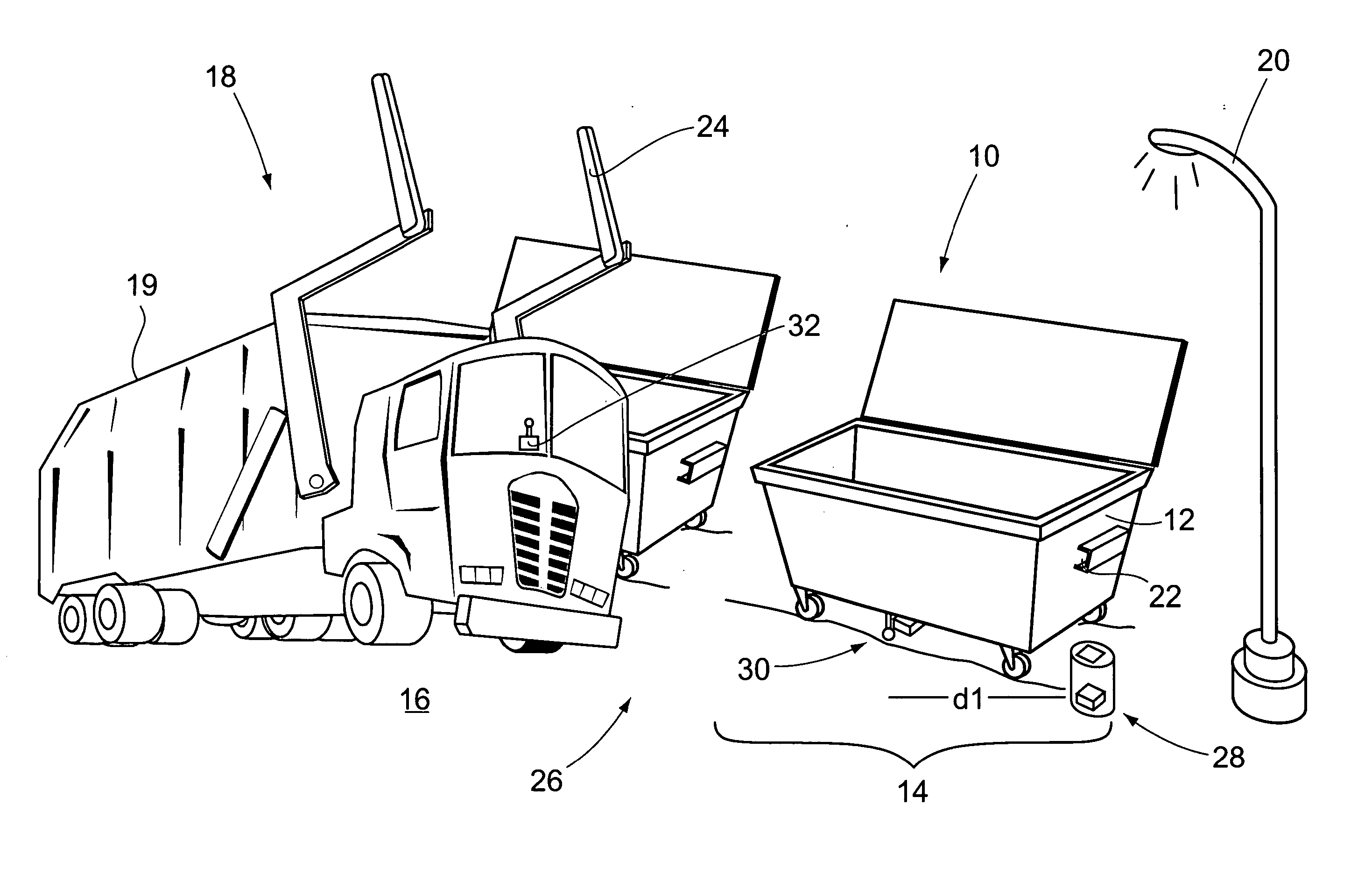
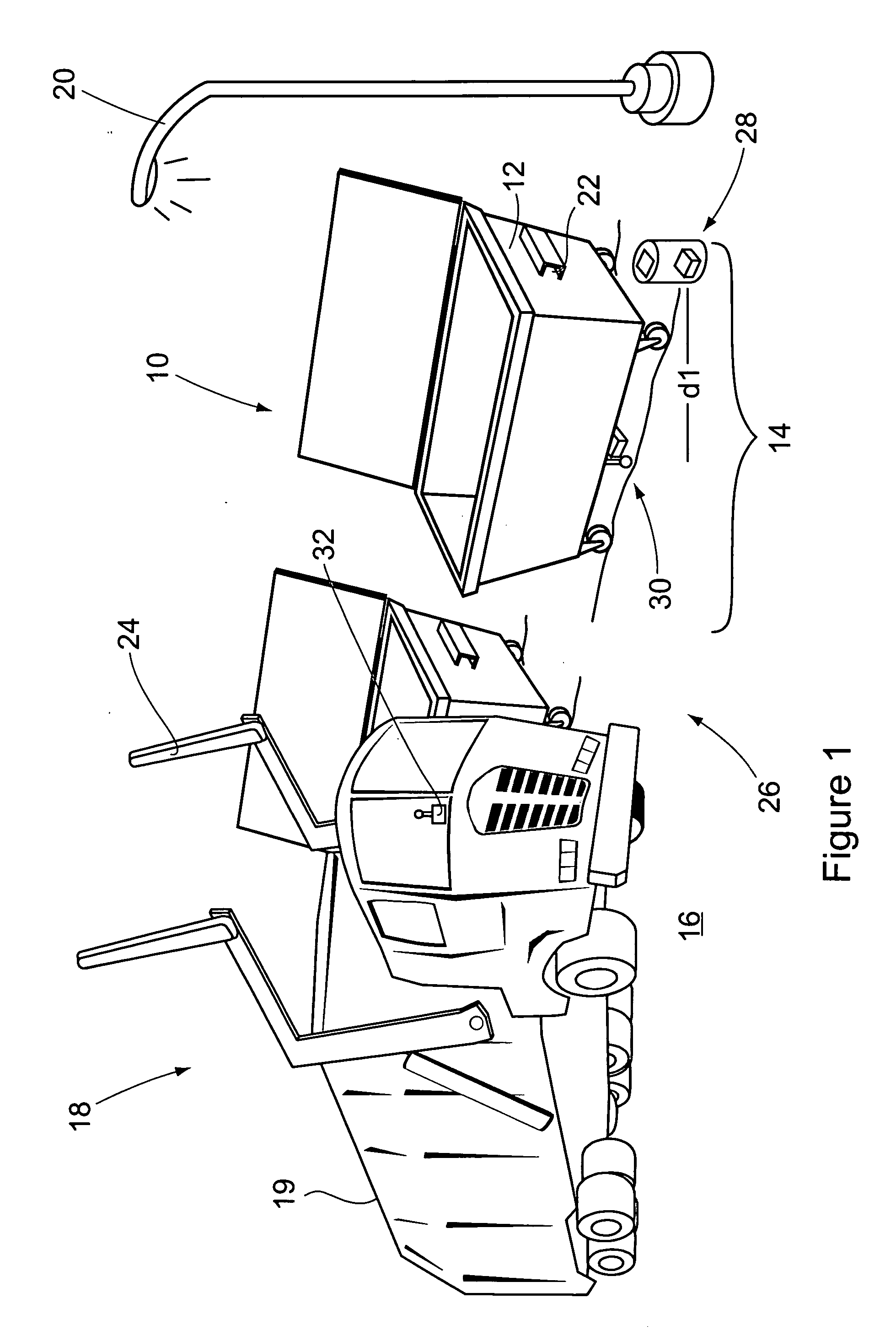
[0020] Referring to the accompanying drawings in which like reference numbers indicate like elements, FIG. 1 illustrates a receptacle station constructed in accordance with a preferred embodiment of the present invention.

[0021] As illustrated in FIG. 1, a typical receptacle station 10 includes space for numerous receptacles 12, a position 14 for each of the receptacles, an area 16 for a truck 18 (or other device) to align with each of the receptacles 12, and structures 20 and other obstructions for which it is desirable to avoid striking them with the receptacles 12 while handling the receptacles 12. In addition, the receptacles include handling aids 22 on their exteriors while the truck 18 includes a mechanism 24 for handling the receptacles 12. An exemplary handling mechanism 24 is shown as a pair of hydraulically operated arms on the refuse truck 18.

[0022] During nominal operations, a truck operator aligns the truck 18 with the receptacle 12 so that the lifting arms 24 can enga...


PUM


Abstract

Methods and apparatus for positively positioning receptacle at a pre-selected location. In a preferred embodiment a system for positioning a receptacle is provided. The system includes a transmitter, a receiver, and an indicator. The transmitter may be on the receptacle and transmits a signal from the current receptacle position. The receiver receives the signal and using the received signal, causes the indicator to indicate whether the receptacle is at the pre-selected position. In other preferred embodiments, the receptacle includes a power supply for the power consuming components on the receptacle. In another preferred embodiment, the transmitter is at the pre-selected position and the receiver is on the receptacle. Methods are also provided which include transmitting and receiving a signal from the current position of the receptacle. From the signal strength it is determined whether the receptacle is at the pre-selected position.

Description

BACKGROUND OF THE INVENTION [0001] 1. Field of the Invention [0002] This invention relates generally to residential and receptacles. More particularly, the present invention pertains to a re-positionable receptacle that is modified with an apparatus that positively locates the receptacle to facilitate emptying the receptacle by a vehicle having articulating arms. [0003] 2. Description of the Related Art [0004] Receptacles are commonly employed to contain raw and purified materials, piece parts, intermediate products, finished products, scrap, and refuse. Because the receptacles tend to fill quickly in manufacturing, residential, and other environments the receptacles typically rest on castors, wheels, or other translation aids to allow them to be easily moved about by the users of the receptacles. Additionally, the receptacles typically include lugs, channels, or other handling aids on their exteriors that enable mechanisms to handle the receptacle, in particular, for lifting and em...

Claims


Application Information

Patent Timeline
Patent Type & Authority Applications(United States)
IPC IPC(8): G08B21/00G08B1/08
CPCB60P1/48B65F1/1484B65F2003/0279B65F2003/022B65F2003/023B65F3/0203B65F2210/128B65F2210/168
Inventor KURPLE, WILLIAM M.JACOBI, C. MICHAEL
Owner CONTINENTAL COMML PRODS
Learn More