Image display unit and method of correcting brightness in image display unit

a technology of image display unit and display unit, which is applied in the direction of cathode-ray tube indicators, static indicating devices, instruments, etc., can solve the problems of inability to obtain corrective data corresponding to unevenness, and inability to achieve final resolution. , to achieve the effect of finer display unevenness, high precision and fine display unevenness

Inactive Publication Date: 2006-03-23
SONY CORP
View PDF5 Cites 34 Cited by
  • Summary
  • Abstract
  • Description
  • Claims
  • Application Information

AI Technical Summary

Benefits of technology

[0037] In the embodiment of the invention, the arrangement of the representative pixel points is set according to display unevenness measured before performing the correction process so that the representative pixel points are arranged with a higher density in a pixel region with relatively finer display unevenness according to display unevenness, so the correction data stored in the storing means is allocated more to the pixel region with relatively finer display unevenness. Thereby, while a correction process with high precision is performed in a pixel region with fine unevenness, a correction process with minimum precision can be performed in a pixel region with rough unevenness through reducing the correction data stored in the storing means. Thereby, while the memory amount is reduced through minimizing the correction data stored in the storing means, the capability of uniformity correction can be improved, compared to a related art.
[0...

Problems solved by technology

However, in the case where no grid point 191 exists as in the case of the B region 193, correction data corresponding to unevenness may not be obtained, so unevenness may not be corrected.
In Japanese Unexamined Patent Application Publication No. 2000-122598, the same issue occurs in the case where correct...

Method used


Image

  • Image display unit and method of correcting brightness in image display unit
  • Image display unit and method of correcting brightness in image display unit
  • Image display unit and method of correcting brightness in image display unit

Examples


Embodiment Construction

[0056] A preferred embodiment will be described in detail below referring to the accompanying drawings.

[0057]FIG. 7 shows the whole structure of an image display unit according to an embodiment of the invention. FIG. 8 schematically shows the structure of a display panel 1 in the image display unit. FIG. 9 schematically shows the structure of a pixel portion of the display panel 1. In the embodiment, an image display unit using an FED as the display panel 1 will be described as an example.

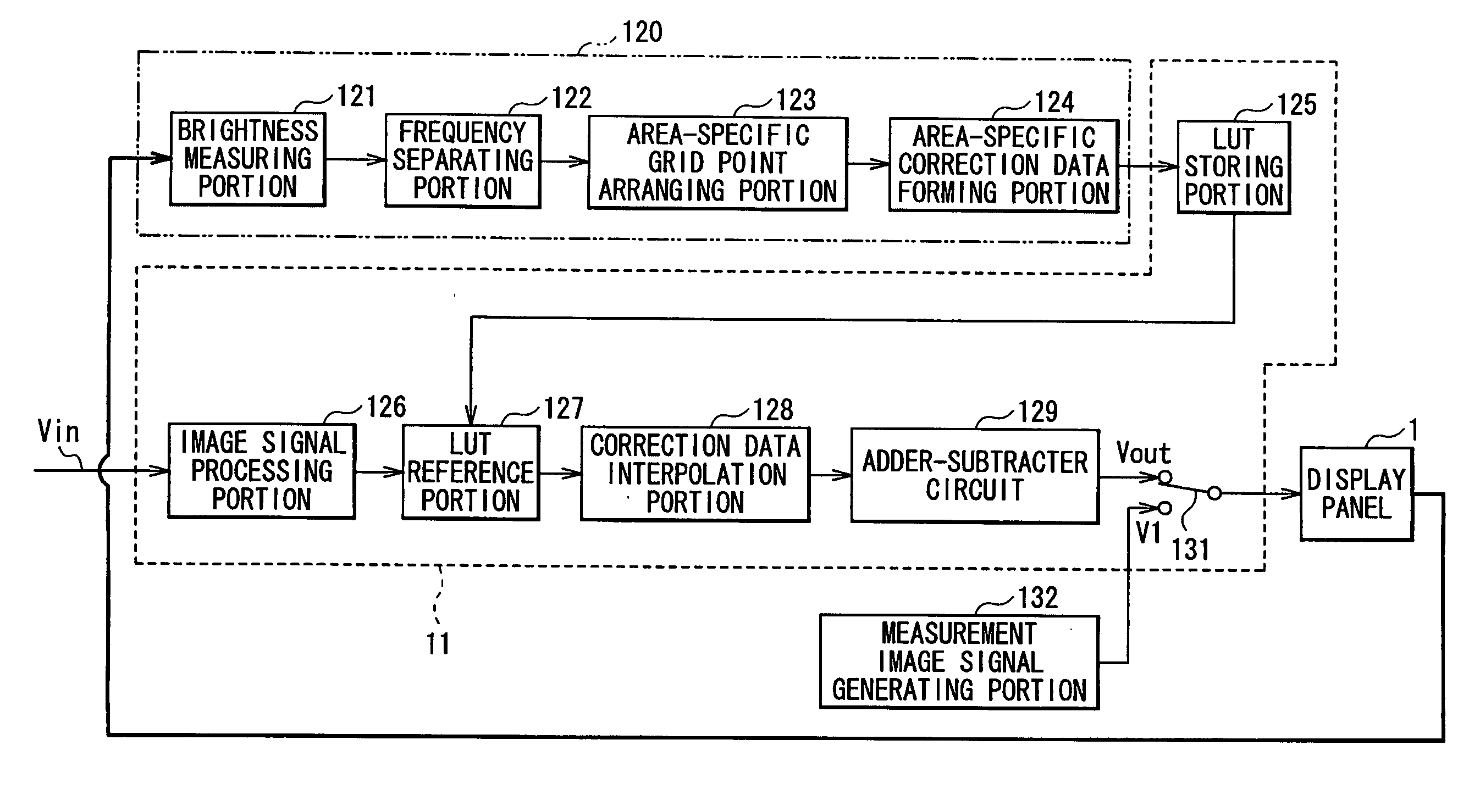
[0058] As shown in FIG. 7, the image display unit includes an A / D (analog / digital) converting portion 10 which converts an analog image signal into a digital signal to output the digital signal, an image signal processing portion 11 which performs various signal processes such as image quality adjustment on a digital image signal, a column direction drive voltage generating portion 13 and a row direction selection voltage generating portion 14 which drive the display panel 1, and a control signal...


PUM


Abstract

While the memory amount is reduced through minimizing correction data prepared in advance, the capability of uniformity correction can be improved, compared to a related art. Correction data for correcting display unevenness between pixels for representative pixel points is stored. Correction data for pixels except for the representative pixel points is calculated by interpolation. The representative pixel points are arranged with a higher density in a pixel region with relatively finer display unevenness.

Description

CROSS REFERENCES TO RELATED APPLICATIONS [0001] The present invention contains subject matters related to Japanese Patent Application JP 2004-274794 filed in the Japanese Patent Office on Sep. 22, 2004 and Japanese Patent Application JP 2005-149280 filed in the Japanese Patent Office on May 23, 2005, the entire contents of which being incorporated herein by reference. BACKGROUND OF THE INVENTION [0002] 1. Field of the Invention [0003] The present invention relates to a display unit which includes a plurality of pixels and controls the level of display brightness on a pixel-by-pixel basis, for example, an image display unit suitable for an FED (Field Emission Display), an EL (Electroluminescence) display, a liquid crystal display unit or the like, and a method of correcting brightness in the image display unit. [0004] 2. Description of the Related Art [0005] In recent years, display units have become thinner and flatter. As one of flat panel display sections (flat panel displays, her...

Claims


Application Information

Patent Timeline
IPC IPC(8): G09G5/00
CPCG09G3/22G09G2360/145G09G2320/0285G09G2320/0233G09G3/20
Inventor MIURA, SATOSHIMOTOE, HISAFUMIYAMAMOTO, YOSUKEMEGURO, TAKEYA
Owner SONY CORP
Why Eureka
Try Eureka