
Constant-velocity joint and image-forming device

Inactive Publication Date: 2006-03-23
NTN CORP
View PDF6 Cites 20 Cited by
  • Summary
  • Abstract
  • Description
  • Claims
  • Application Information

AI Technical Summary

Benefits of technology

[0016] Preferably, a tapered surface is formed so as to extend from one axial end of each of the track grooves that is near the axial end of the annular space to the axial end of the annular space, the tapered surfaces having a diameter that gradually increases toward the axial end of the annular space. With this arrangement, the balls can be easily inserted into the tapered surfaces. With the balls inserted in the respective tapered surfaces, simply by rotating the outer ring and the cage relative to each other, the balls can be guided smoothly into the track grooves. Thus, even if the balls are not accurately axially aligned with the respective track grooves, the balls can be smoothly inserted into the respective grooves, so that the constant-velocity joint can be assembled easily.
[0027] Since the constant-velocity joint can be easily assembled and disassembled simply by inserting the cage into the outer ring and pulling the cage out of the outer ring, parts of the image forming device such as the photoconductor drum can be easily replaced with new ones. Maintenance of the image forming device is thus easy. Since no lubrication with grease is necessary, it is possible to completely eliminate the possibility of the transfer material A being soiled with grease.

Problems solved by technology

Thus, in order to assemble and disassemble the constant-velocity joint, it is necessary to mount and dismount the boot, which is troublesome, so that it is extremely troublesome to replace any damaged or broken parts of the input and output devices between which torque is transmitted through the constant-velocity joint.
While such conventional constant-velocity joints made of a metal are high in strength, they are heavy, need grease lubrication, and tend to produce large operating noise.
Their use is therefore limited.
For example, they are not suitable for use in office machines, audio devices, medical instruments, food producing machines, household appliances, etc.
Although this publication proposes to arrange the exposure position and the transfer position diametrically opposite to each other, it is actually difficult to arrange the above two positions exactly diametrically opposite to each other due to assembling errors and / or inclination of the photoconductor drum.
Thus, it will be difficult to completely cancel any shrinkage and expansion of the latent image with the shrinkage and expansion of the toner image.
The ultimately obtained image thus tends to be low in quality.
Further, such non-constant-velocity joints do not permit easy disassembling of the input and output devices that are coupled together thorough the joint.
In particular, it is troublesome to replace parts of the image forming device such as the photoconductor drum.
Maintenance is thus difficult.

Method used


Image

  • Constant-velocity joint and image-forming device
  • Constant-velocity joint and image-forming device
  • Constant-velocity joint and image-forming device

Examples


Embodiment Construction

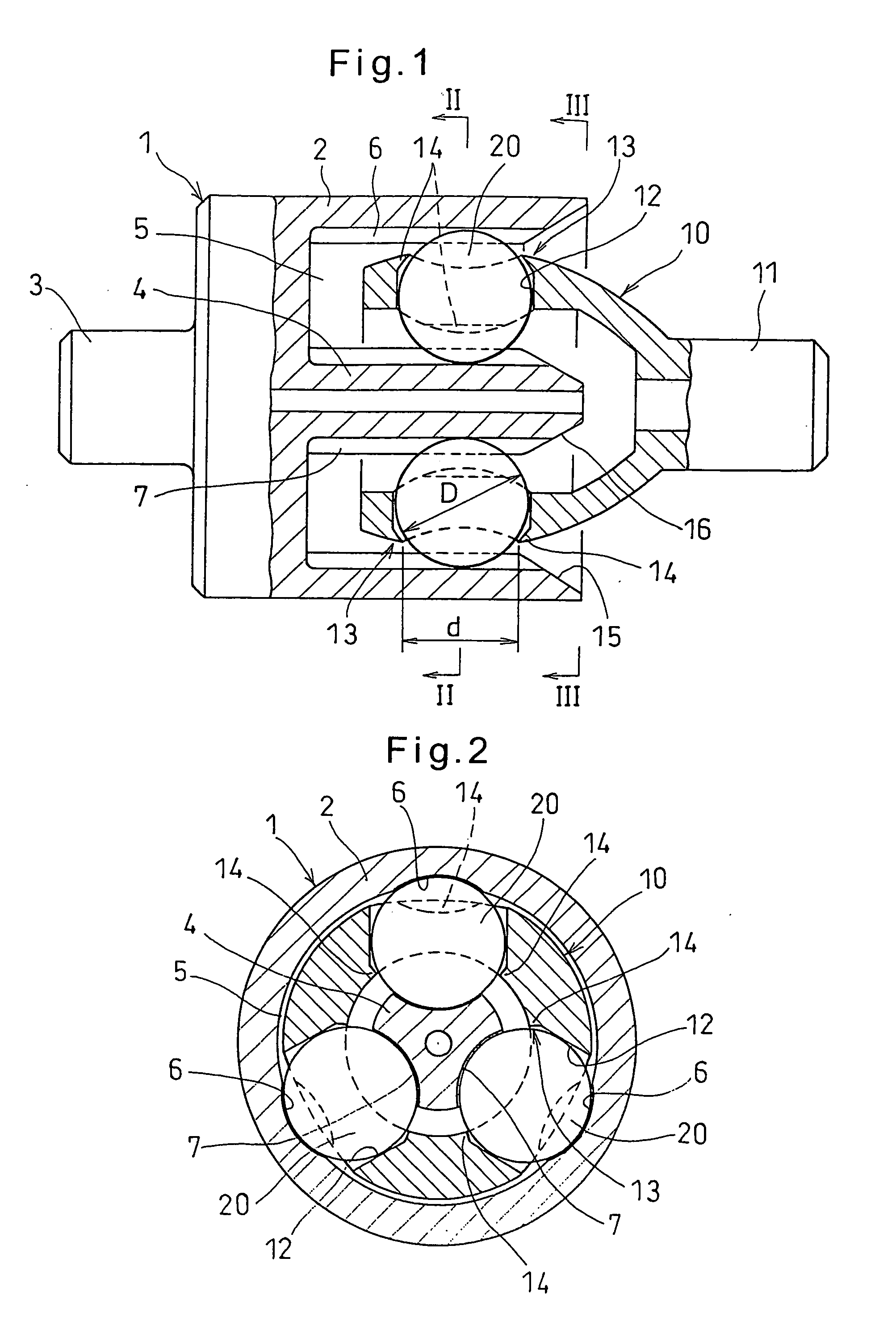
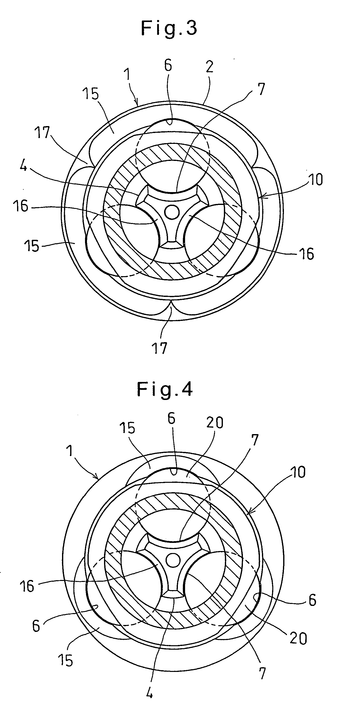
[0035] Now referring to the drawings, FIGS. 1 and 2 show the constant-velocity joint embodying the present invention. It comprises an outer ring 1, a cage 10 and balls 20.

[0036] The outer ring 1 includes a cup 2 having an opening at one end, and an end wall closing the other end thereof. A first shaft 3 is integrally formed on the outer surface of the end wall of the cup 2. A guide shaft 4 extends from the inner surface of the end wall along the axis of the outer ring 1 to define an annular space between the guide shaft 4 and the cup 2. Three track grooves 6 and three track grooves 7 are formed in the radially inner surface of the cup 2, which defines the radially outer wall of the annular space 5, and in the outer surface of the guide shaft 4, which defines the radially inner wall of the annular space 5, respectively. The track grooves 6 and 7 are circumferentially spaced apart from each other at equal intervals of 120 degrees.

[0037] The track grooves 6 or the track grooves 7 may...


PUM


Abstract

A constant-velocity joint includes an outer ring formed with an annular space therein having an opening at one axial end thereof. The annular space is defined by a radially outer wall and a radially inner wall of the outer ring. One of the radially outer wall and the radially inner wall is formed with three axially extending track grooves circumferentially spaced apart from each other by 120 degrees. A cage is inserted in the annular space and formed with pockets at positions corresponding to the respective track grooves. Balls are each received in one of the pockets so as to roll along one of the track grooves. A pair of diametrically opposed protrusions is formed at radially inner and outer open ends of the respective pockets of the cage to prevent the balls from coming out of the respective pockets of the cage.

Description

BACKGROUND OF THE INVENTION [0001] This invention relates to a constant-velocity joint through which a driving shaft and a driven shaft are adapted to be coupled together so as to transmit torque from the driving shaft to the driven shaft and an image forming device. [0002] A constant-velocity joint is typically used to transmit torque from a vehicle drive shaft to an axle. [0003] Through such a constant-velocity joint, torque can be transmitted from a driving shaft to a driven shaft such that the driven shaft is rotated at a constant speed even if the angle between the driving shaft and the driven shaft varies. Thus, constant-velocity joints are used in various industrial machines other than motor vehicles, too. [0004] There are known two types of constant-velocity joints, i.e. fixed type constant-velocity joints, which only allow the driving and driven shafts to incline relative to each other, and sliding type constant-velocity joints, which allow the driving and driven shafts not...

Claims


Application Information

Patent Timeline
IPC IPC(8): H04N1/29
CPCF16D3/227H04N1/29G03G15/757Y10S464/906
Inventor YAMAZAKI, MASAYUKIFUKUZAWA, SATORUOHASHI, MASAAKI
Owner NTN CORP
Features
  • Generate Ideas
  • Intellectual Property
  • Life Sciences
  • Materials
  • Tech Scout
  • Unparalleled Data Quality
  • Higher Quality Content
  • 60% Fewer Hallucinations
Learn More