Hybrid power supply system having energy storage device protection circuit

a protection circuit and power supply system technology, applied in the direction of electric devices, battery/fuel cell control arrangement, primary cell maintenance/service, etc., can solve the problems of severe system performance loss, power supply system output voltage could drop below the level required for safe vehicle operation, and potential problems

Inactive Publication Date: 2006-03-23
CELLEX POWER PRODS
View PDF24 Cites 56 Cited by
  • Summary
  • Abstract
  • Description
  • Claims
  • Application Information

AI Technical Summary

Benefits of technology

[0007] The system may be used as a power supply in an electric vehicle having an active dynamic load. The energy storage device may comprise, for example, one or more batteries, capacitors, supercapacitors or ultracapacitors. The power generator may comprise a fuel cell.
[0008] The system is operable in a normal operating mode and in a de-rated operating mode. The controller maintains the switch in a closed position in the normal operating mode and opens the switch in the de-rated operating mode. Preferably a sensor is also provided which is operatively coupled to the controller. The controller switches the system from the normal operating mode to the de-rated mode when the sensor detects a predetermined operating condition. For example, the sensor could monitor at least one parameter related to the state of charge of the energy storage device and detect the predetermined operating condition when a predetermined threshold value is reached. The at least one parameter could, for example, be voltage, current, temperature, internal resistance and chemistry change.

Problems solved by technology

Problems may potentially arise, however, in the case of malfunction of power system components.
For example, if a battery becomes low in residual charge or is over-discharged, intervention is required to protect the battery before a critical point is reached beyond which damage to the battery or a severe loss of system performance will occur.
Many of these systems involve disconnecting the battery from the load or introducing some in-line impedance that will provide a limited power to the load.
However, in many prior art applications if the load is increasing and demanding more current, the output voltage of the power supply system could drop below levels required for safe vehicle operation.
Some stand-alone systems are known in the prior art which do not permit the power supply system to continue to service the load in a de-rated mode.

Method used


Image

  • Hybrid power supply system having energy storage device protection circuit
  • Hybrid power supply system having energy storage device protection circuit
  • Hybrid power supply system having energy storage device protection circuit

Examples


Embodiment Construction

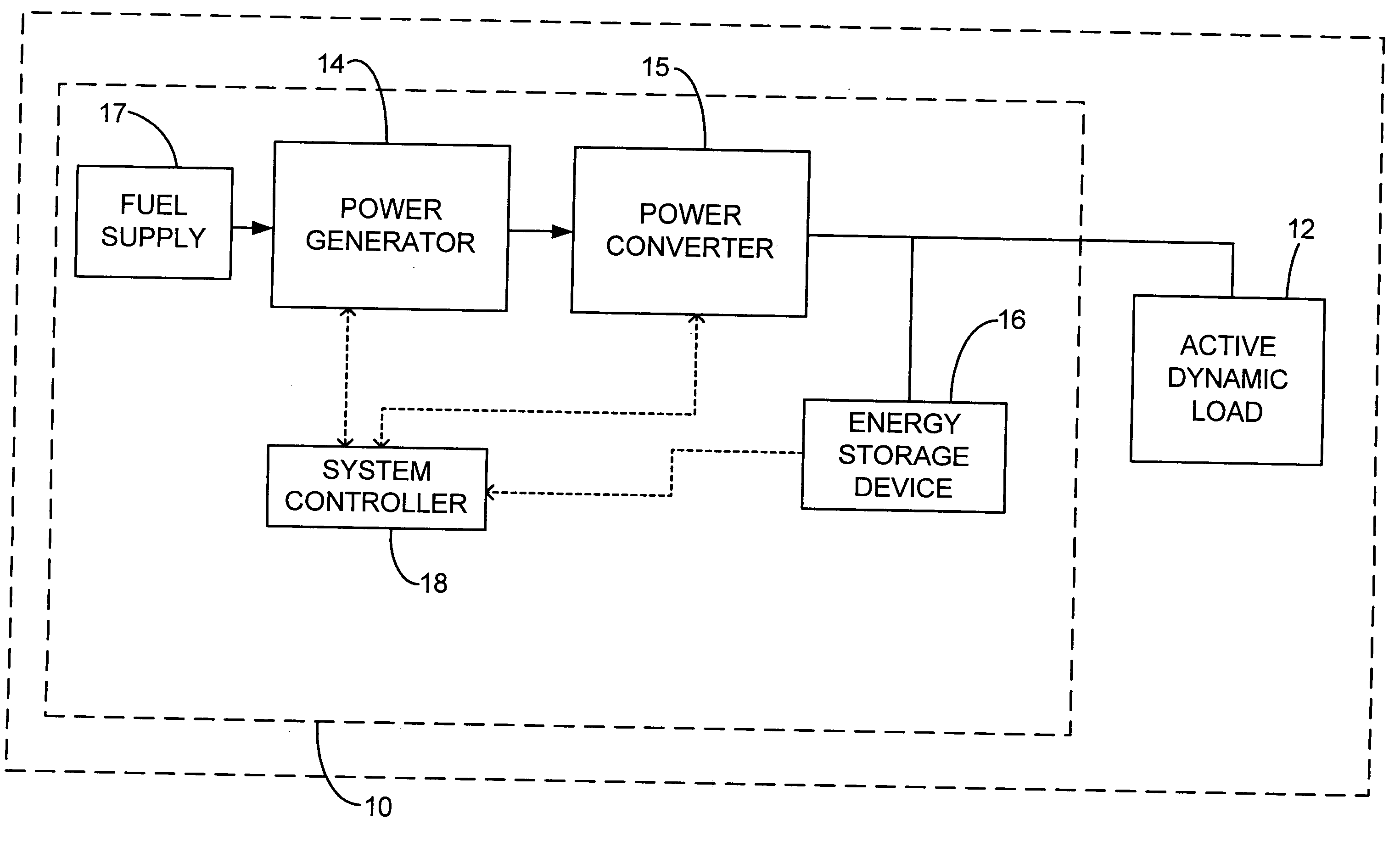
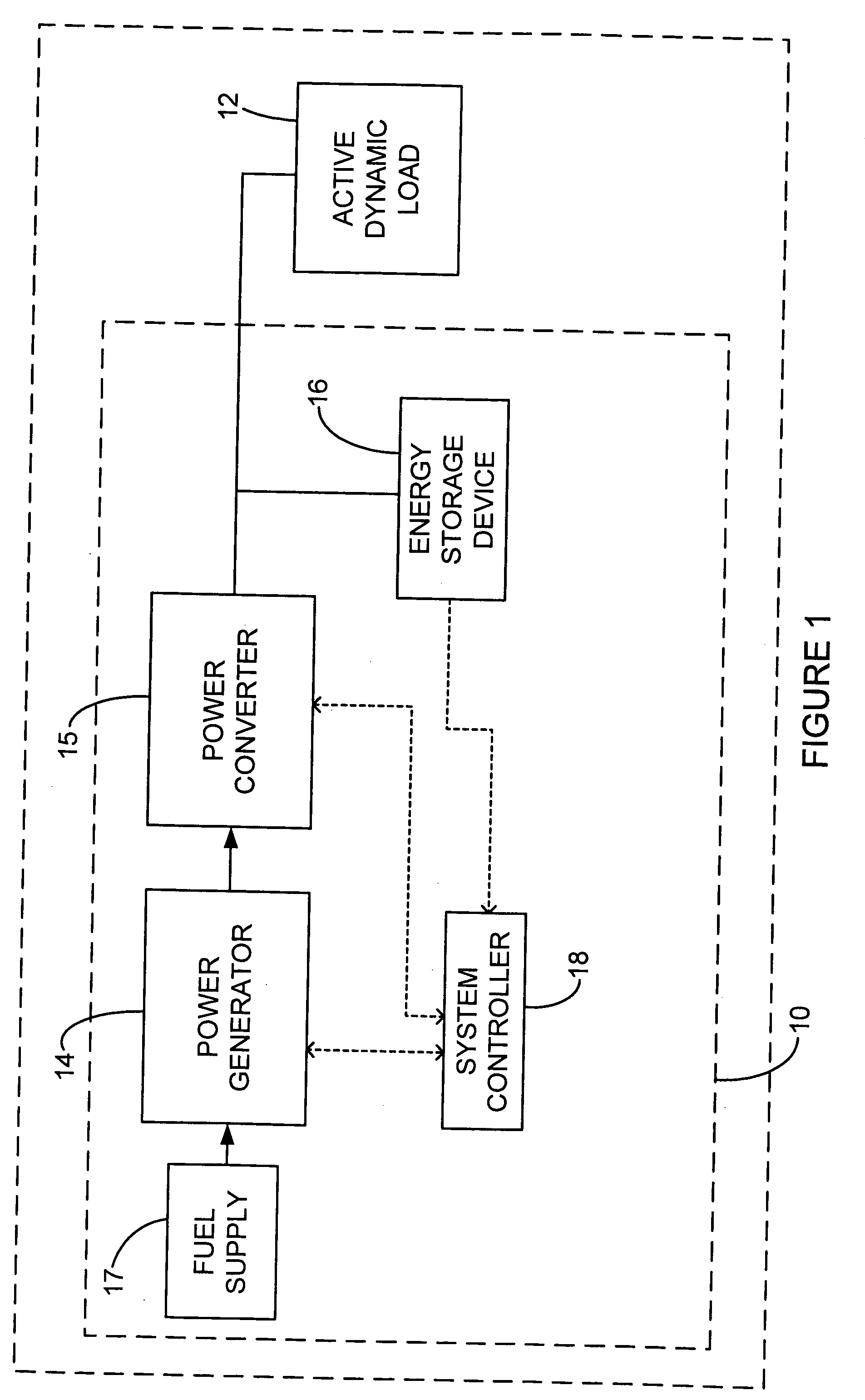
[0020]FIG. 1 is a schematic view of a hybrid power supply system 10 of the prior art for delivering power to an active dynamic load 12. For example, power supply system 10 could supply power to a forklift truck drive or other similar load 12. Hybrid power supply system 10 comprises a power generator 14, a power converter 15, an energy storage device 16 and a system controller 18. Preferably power generator 14 is sized to provide the average power requirements of the load and energy storage device16 is sized to provide at least the peak power requirements. For example, power generator 14 may comprise a fuel cell receiving fuel from a fuel supply 17. Power converter 15 adapts the power generated by generator 14 to a DC format suitable for use by load 12. Energy storage device 16 may comprise one or more batteries, capacitors, supercapacitors or ultracapacitors. System controller 18 controls the delivery of power from power generator 14 and / or energy storage device 16 depending upon th...


PUM


Abstract

This application relates to an energy storage device protection circuit for use in a hybrid system supplying power to an active dynamic DC load, such as an electric vehicle drive. The circuit prevents over-discharge of the energy storage device and ensures that the system will be capable of delivering a minimum acceptable level of power to the load, even when the energy storage device is in a low state of charge or other de-rated mode. The hybrid system includes a power generator such as fuel cell capable of supplying at least the average power value requirements of the load and an energy storage device such as a battery or capacitor capable of supplying at least the difference between the peak power requirements of the load and the average power value. A controller is provided for controlling the relative supply of power to the load from the power generator and the energy storage device. The protection circuit is in series with the energy storage device and may include a first switch controllable by the controller, a diode in parallel with the first switch and optionally a current-limiting impedance in parallel with the first switch. The system may be implemented in lift trucks and the like to prevent overdriving of the vehicle in a low state of charge condition while permitting the operator to safely return the vehicle to a service location. The system regulates the output of the fuel cell in both the normal and de-rated operating modes to avoid load-following operation.

Description

TECHNICAL FIELD [0001] This application relates to an energy storage device protection circuit for use in a hybrid electrical system supplying power to an active dynamic DC load, such as an electric vehicle. The circuit prevents over-discharge of the battery or other energy storage device and ensures that the system will be capable of delivering a minimum acceptable level of power to the load, even when the energy storage device is in a low state of charge or other fault condition. BACKGROUND OF THE INVENTION [0002] Hybrid power supply systems are well known in the prior art for supplying power to loads having fluctuating power requirements. For example, a hybrid power supply system for use in non-road electric vehicles, such as lift trucks and the like, is described in applicant's co-pending U.S. patent application Ser. No. 10 / 684,622 which is hereby incorporated by reference in its entirety. Lift trucks have a duty cycle that is characterized by loads which fluctuate substantially...

Claims


Application Information

Patent Timeline
Patent Type & Authority Applications(United States)
IPC IPC(8): H02H7/06
CPCB60L3/0046B60L3/0053B60L11/1887B60W10/08B60W10/26B60W10/28Y02T90/34B60W20/102H01M6/50H01M16/006H02J7/34H02J2001/004B60W20/00B60W20/11B60L58/40H02J2300/30B60L58/14B60L58/15B60L58/30Y02T90/40Y02T10/70Y02E60/50Y02E60/10B60W2510/246B60W2510/244B60W20/13
Inventor MIHAI, RASVAN CATALINTRANDAFIR, EUGENE ANDREILEBOE, DAVID
Owner CELLEX POWER PRODS
Why Eureka
Try Eureka