Band-limited polarity detection

a polarity detection and band-limited technology, applied in the direction of stereophonic circuit arrangements, instruments, measurement devices, etc., can solve the problems of poor sound reproduction or other audio artifacts, affecting the quality of the sound reproduction, and the consumer's experience of proper setting up such home theater systems, so as to achieve the effect of not incurring any significant additional hardware costs

Inactive Publication Date: 2006-03-23
CIRRUS LOGIC INC
View PDF8 Cites 24 Cited by
  • Summary
  • Abstract
  • Description
  • Claims
  • Application Information

AI Technical Summary

Benefits of technology

[0027] As noted in the co-pending parent Patent Applications previously incorporated by reference, an adaptive filtering system may be used to measure speaker placement, and similar hardware used to determine equalization. Thus, the speaker polarity detection system of the present invention can be added to a product containing one or more of these previous features, without any significant additional hardware cost.

Problems solved by technology

However, properly setting up such Home Theater systems can sometimes be problematic for the consumer.
One problem with such systems is they may require the consumer to unpack the various components of the system, place the components in optimal positions around the room, and then wire the components together.
If one speaker in the system is connected using a reverse polarity, it may generate sound out of phase with the other speakers, causing degradation in the sound reproduction or other audio artifacts.
Unfortunately, the wires often used for speaker wire are marked in a manner that can be difficult to read.
All of these Prior Art approaches have limitations.
The printed or embossed indicia are often difficult to discern for a consumer and can be readily reversed without much effort.
In all situations, however, the main problem is that the consumer can easily forget which lead was selected as the “positive” (or “red”) lead of the speaker wire pair, and thus end up connecting some speakers in one polarity and other speakers in a different polarity.
The problem with this approach is that for higher-powered systems, such connections may be inadequate, as larger gauge speaker wire may be needed than the thin coaxial cables provided with such RCA-type connections.
Unfortunately, hiring an acoustician to fine tune a home theater system is expensive.
Some of these systems can detect whether left and right speakers are out-of-phase with each other, but not whether individual speakers are wired with the correct polarity.
However, such systems report only whether left and right speaker pairs are wired with the same polarity.
Systems known in the art which report wiring problems on a per-speaker basis also exist, but such systems are often inaccurate and do not work for all types of speakers, as they do not compensate for the internal wiring of some speakers, which may have the tweeter wired backward from the woofer.

Method used


Image

  • Band-limited polarity detection
  • Band-limited polarity detection
  • Band-limited polarity detection

Examples


Embodiment Construction

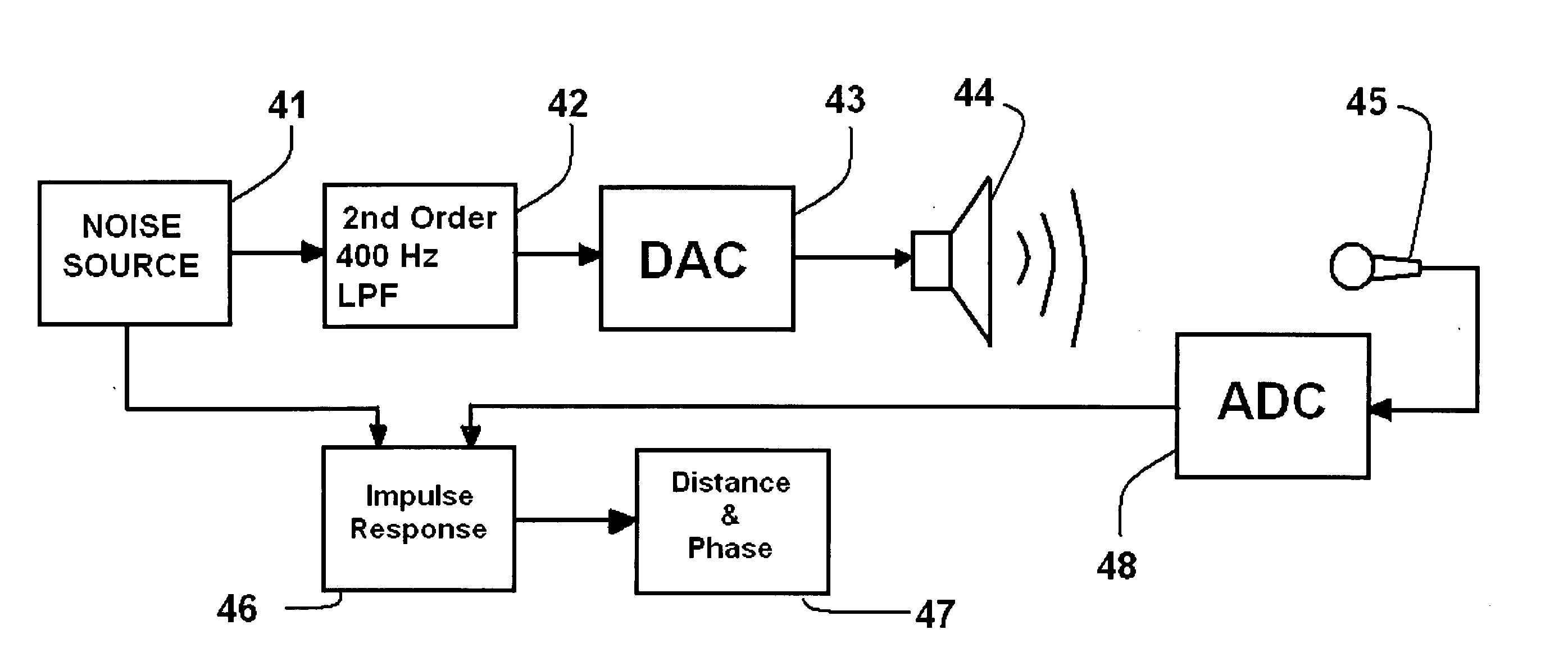
[0036]FIG. 3 is a block diagram of the apparatus of the present invention employing an adaptive filter for polarity detection. For the sake of simplicity, many of the basic components in an auto-setup home theater system are not illustrated here. Referring to FIG. 3, a noise source 41 may be used to generate a sound pattern or series of impulses or the like. As discussed above, this sound source could comprise a number of sound patterns generated from a stored sound pattern or generated spontaneously.

[0037] In this embodiment, the output of noise source 41 may first be passed through a second order 400 Hz low pass filter 42 to pass only those frequencies substantially below 400 Hz. A Digital to Analog Converter (DAC) 43 converts this digital sound pattern into an analog signal, which is then driven through speaker 44.

[0038] The digital signal from noise source 41 may also be sent as an input to impulse response generator 46, which in the preferred embodiment is an adaptive filter....


PUM


Abstract

Individual speaker polarity is detected by band-limiting the processing to a range where the impulse response of most speakers are in-phase with their wiring. In the preferred embodiment, a second order 400 Hz Low Pass Filter (LPF) is used to band-limit the processing. Filtering can occur prior to processing as part of the noise generation, or completely as a post-processing operation on a full-bandwidth impulse response. Applying the low pass filter eliminates artifacts in the impulse response due to reverse-polarity wired drivers in a speaker system (e.g., tweeter). By analyzing only the lower frequencies, the initial peak of the impulse response will correlate to speaker polarity in the system.

Description

CROSS-REFERENCE TO RELATED APPLICATIONS [0001] The present application claims priority from Provisional U.S. Patent Application No. 60 / 612,474 filed on Sep. 23, 2004 (Cirrus Logic Docket No. 1537-DSP), and incorporated herein by reference. The present application is also a Continuation-In-Part of U.S. patent application Ser. No. 11 / 002,102 entitled “TECHNIQUE FOR SUBWOOFER DISTANCE MEASUREMENT”, filed on Dec. 3, 2004 (Cirrus Logic Docket No. 1538-DSP), and incorporated herein by reference. The present application is also a Continuation-In-Part of U.S. patent application Ser. No. 11 / 038,577, filed on Jan. 21, 2005 (Cirrus Logic Docket No. 1539-DSP), and incorporated herein by reference. The present application is also a Continuation-In-Part of U.S. patent application Ser. No. UNASSIGNED filed on Feb. 14, 2005 (Cirrus Logic Docket No. 1540-DSP), and incorporated herein by reference. FIELD OF THE INVENTION [0002] The present invention relates to a method and apparatus for calibrating a...

Claims


Application Information

Patent Timeline
Patent Type & Authority Applications(United States)
IPC IPC(8): H04R29/00
CPCG01S11/14H04S7/301H04R29/001H04R5/04
Inventor MCKEE COOPER, JOEL C.NOSO, NORITOSHI
Owner CIRRUS LOGIC INC
Why Eureka
Try Eureka