Lens driving device, imaging device using the same, and small-sized electronics device using the same

a driving device and lens technology, applied in the field of lenses driving devices, can solve the problems of insufficient image function and image data quality, decentering of stator and hollow rotor coaxially, and unbalance of attractive force and repulsive force, and achieve the effect of increasing electric power consumption

Active Publication Date: 2006-03-23
NANCHANG O FILM OPTICAL ELECTRONICS TECH CO LTD +1
View PDF5 Cites 26 Cited by
  • Summary
  • Abstract
  • Description
  • Claims
  • Application Information

AI Technical Summary

Benefits of technology

[0011] In view of the foregoing, it is a primary object of the present invention to provide a lens driving device for moving a taking lens in an optical-axis direction, in which electric power consumption is reduced.
[0012] It is a second object of the present invention to provide an imaging device using the above-mentioned lens driving device, in which electric power consumption is reduced.
[0016] According to the present invention, the rotor is attracted in the axial direction when the respective stators are activated to rotate the rotor. Thus, the rotor and the rotary barrel are prevented from being attracted in a direction perpendicular to the optical axis, even if the rotor and the stators are rotated in an eccentric state. It is prevented that electric power consumption increases due to friction with a cover holding the rotary barrel. Further, it is prevented that abnormal noise occurs due to the friction with the cover.

Problems solved by technology

Due to this, an image function and quality of the obtained image data are insufficient.
Thus, there arises a problem in that the stator and the hollow rotor coaxially disposed are decentered.
If the hollow rotor is rotated in the decentered state, unbalance is caused regarding attractive force and repulsive force, and the hollow rotor is attracted to a side nearing the stator.

Method used


Image

  • Lens driving device, imaging device using the same, and small-sized electronics device using the same
  • Lens driving device, imaging device using the same, and small-sized electronics device using the same
  • Lens driving device, imaging device using the same, and small-sized electronics device using the same

Examples


Embodiment Construction

)

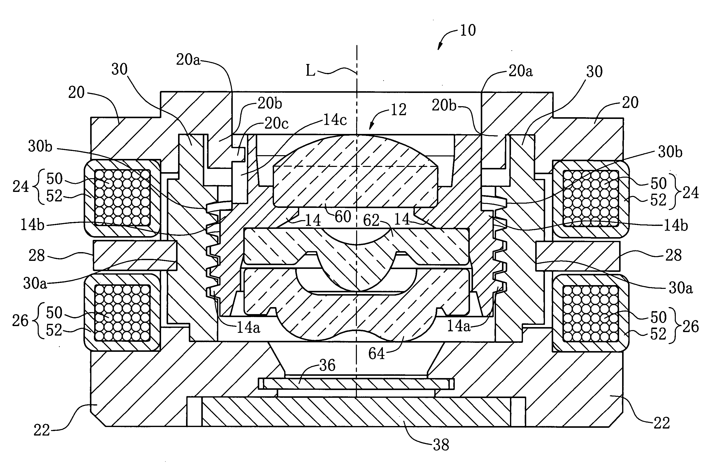
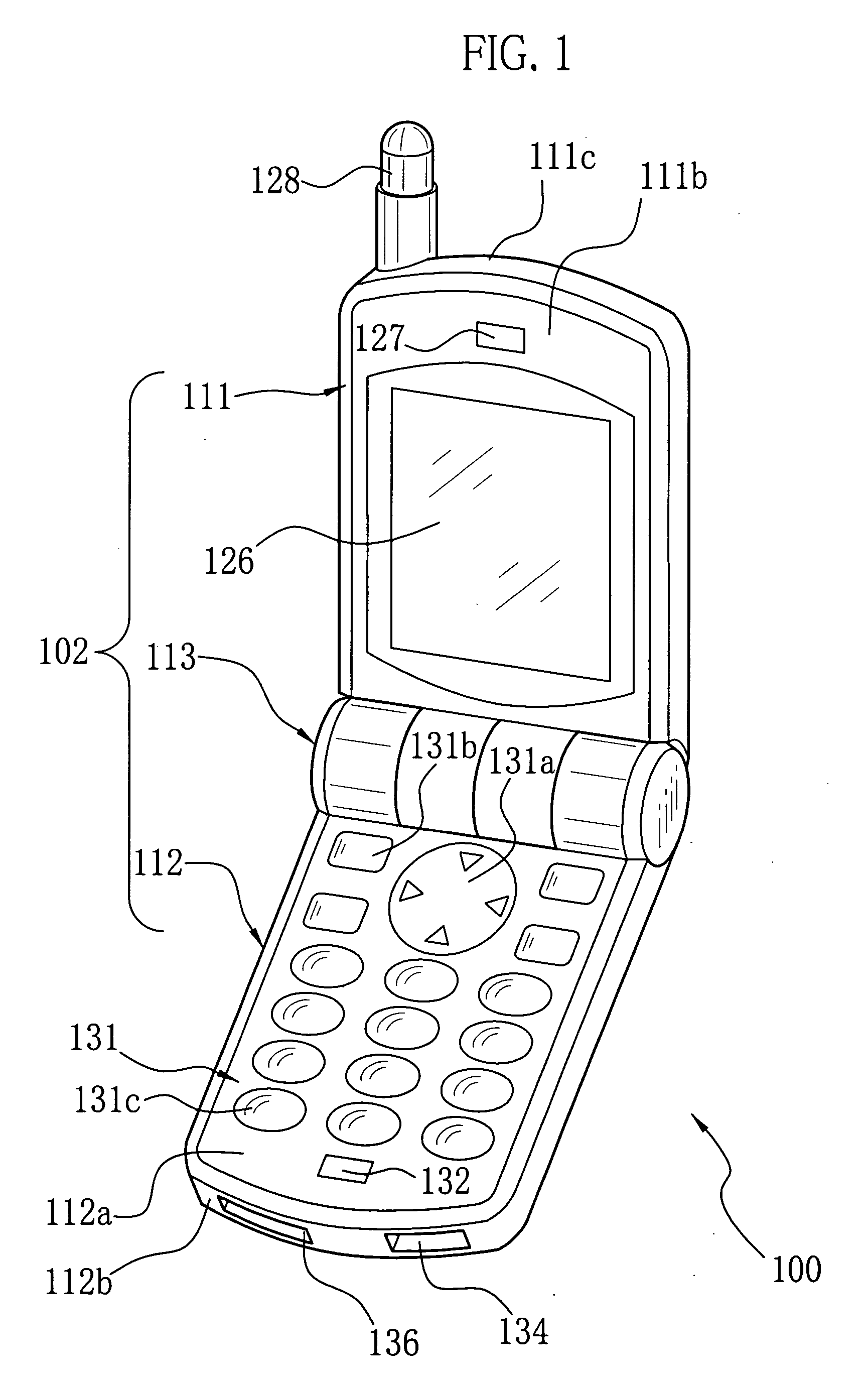
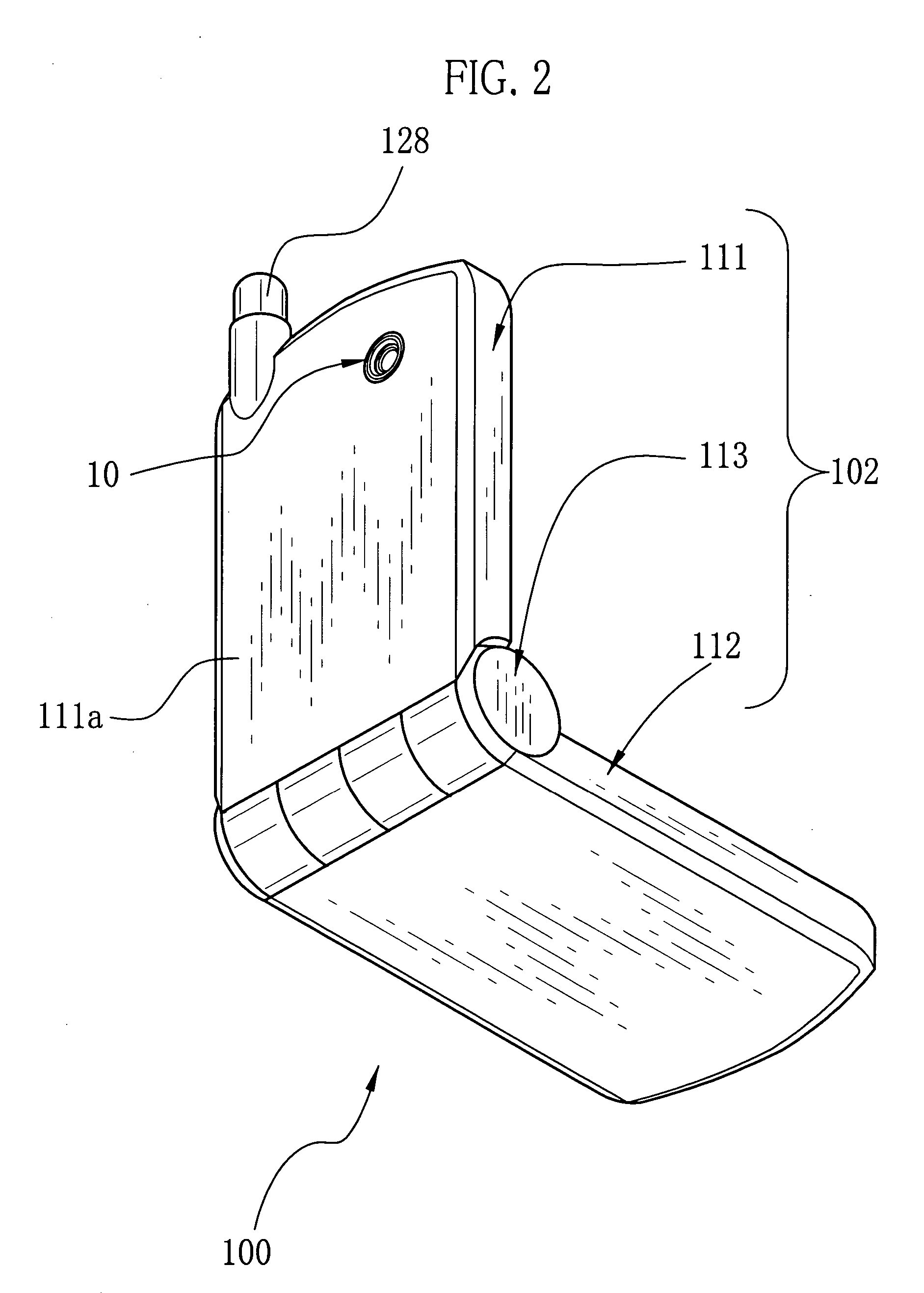
[0028]FIGS. 1 and 2 are external perspective views respectively showing a front side and a rear side of a camera-equipped cell-phone comprising an imaging device according to the present invention. A main body 102 of the camera-equipped cell-phone 100 includes an upper body 111, a lower body 112 and a hinge 113 rotatably connecting the respective bodies 111 and 112.

[0029] As shown in FIG. 2, the upper body 111 is provided with the imaging device 10 according to the present invention. The camera-equipped cell-phone 100 obtains image data from the imaging device 10. The hinge 113 is provided with a clicking mechanism (not shown) for retaining the upper and lower bodies 111 and 112 at a predetermined angle during a usage time of the camera-equipped cell-phone 100. It is possible to open and fold the upper and lower bodies 111 and 112 by rotating the main body 102 around the hinge 113. When the camera-equipped cell-phone 100 is not used, the upper and lower bodies 111 and 112 are fold...


PUM


Abstract

An imaging device moves a taking lens in an optical-axis direction by a hollow stepping motor of a claw-pole type comprising a disk-shaped hollow magnet and stators. The magnet is disposed in a direction perpendicular to the optical axis. The stators are respectively adjacent to both surfaces of the magnet in the optical-axis direction. When the magnet is rotated, attractive force caused by the respective stators is applied in the optical axis direction. It is prevented that the magnet and a rotary barrel are attracted in the direction perpendicular to the optical axis. Thus, electric power consumption is prevented from increasing due to friction with upper and lower covers, and abnormal noise is prevented from occurring due to the friction.

Description

BACKGROUND OF THE INVENTION [0001] 1. Field of the Invention [0002] The present invention relates to a lens driving device for moving a lens in an optical-axis direction, and further relates to an imaging device and a small-sized electronics device using this lens driving device. [0003] 2. Description of the Related Art [0004] Small-sized electronics devices are widely used. As to this kind of the electronics devices, there are a cell-phone, a PDA (Personal Digital Assistant) and so forth having a built-in imaging device for taking a subject image and obtaining digital image data. Since the small-sized electronics device carried around comprises the imaging device, shooting is easily performed at any time without carrying a digital still camera, a digital video camera or the like. Moreover, it is general that this kind of the small-sized electronics device preliminarily has a data communication function utilizing infrared rays and so forth. Thus, there is an advantage that it is pos...

Claims


Application Information

Patent Timeline
Patent Type & Authority Applications(United States)
IPC IPC(8): G03B17/00
CPCG02B7/102G02B13/0035H02K37/125G03B29/00H02K7/06G02B13/009
Inventor NAKA, YOJISENBA, TAKEHIKOMANABE, MITSUO
Owner NANCHANG O FILM OPTICAL ELECTRONICS TECH CO LTD
Why Eureka
Try Eureka