
Sprinkler apparatus and related methods

Active Publication Date: 2006-03-30
NEPTUNE BENSON INC
View PDF6 Cites 13 Cited by
  • Summary
  • Abstract
  • Description
  • Claims
  • Application Information

AI Technical Summary

Benefits of technology

[0005] The present invention may further be configured to balance or otherwise create an approximately equal and opposite axial fluid forces within the apparatus nozzle (the rotational force remains, in order to provide the desired nozzle rotation). More specifically, the invention provides an approximately equal downward force to neutralize the normal upward thrust caused by the water as it flows out the rotary shaft and throw arm of the apparatus. Preferably, the apparatus includes flow path and seal elements (such as a cup seal or similar sealing mechanism) acting on the rotary arm such as near its inlet. This helps reduce or eliminate a problem that, in many rotary sprinklers, may cause premature bearing and / or seal failure.

Problems solved by technology

Some of these sprinklers are mechanically complex, and include a relatively large number of interconnected parts to rotate and control the sprinkler nozzle.
In addition, some parts are subject to substantial friction or other wear caused by the water pressure itself and the rotation of the sprinkler during use.

Method used


Image

  • Sprinkler apparatus and related methods
  • Sprinkler apparatus and related methods
  • Sprinkler apparatus and related methods

Examples


Embodiment Construction

[0019] Embodiments of the present invention will now be described with references to the accompanying Figures, with like reference numerals referring to like elements throughout. The terminology used in the description is not intended to be interpreted in any limited or restrictive manner, simply because it is being utilized in conjunction with a detailed description of certain embodiments of the invention. Furthermore, various embodiments of the invention (whether or not specifically described) may include novel features, no single one of which is solely responsible for its desirable attributes or which is essential to practicing the invention.

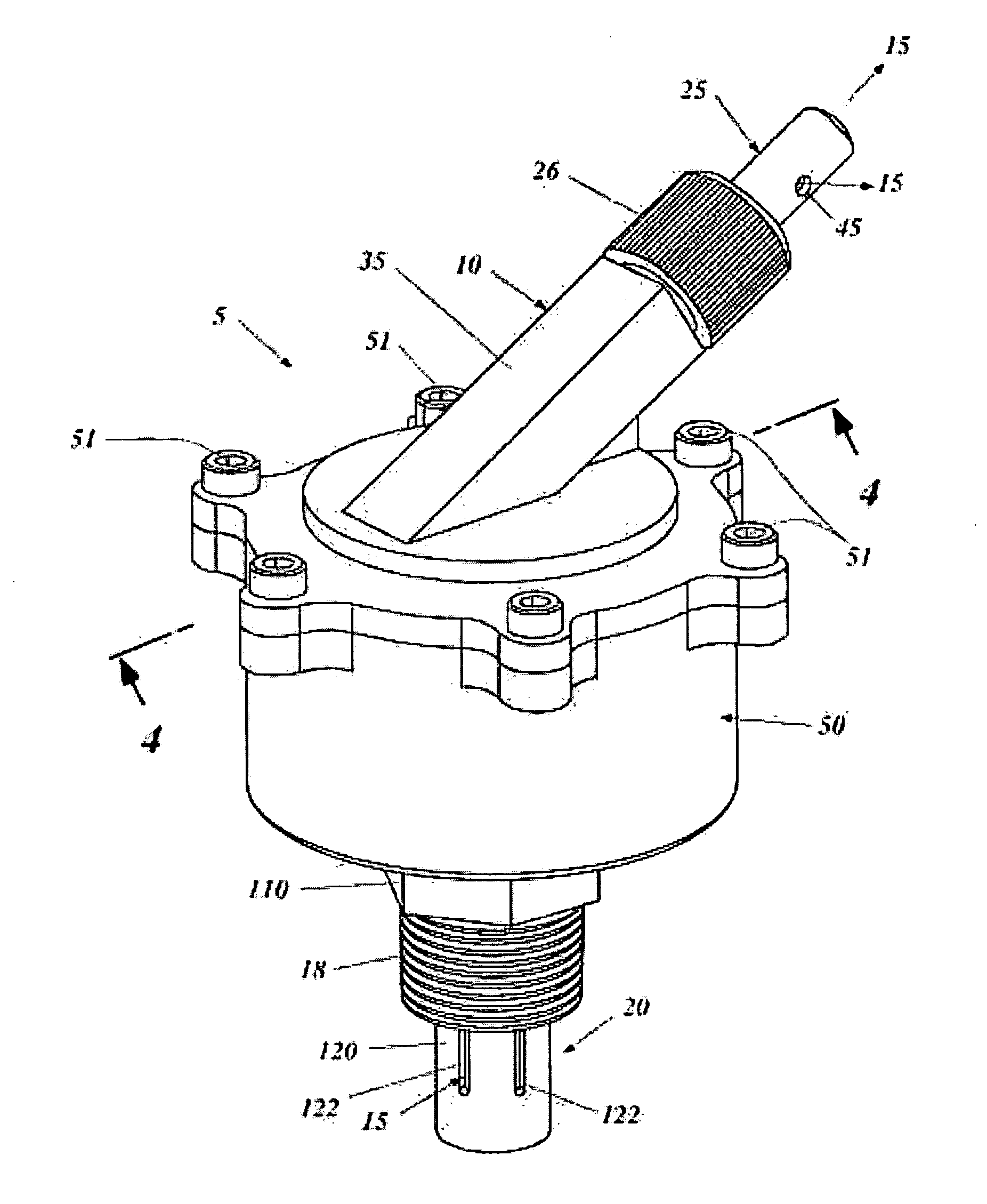
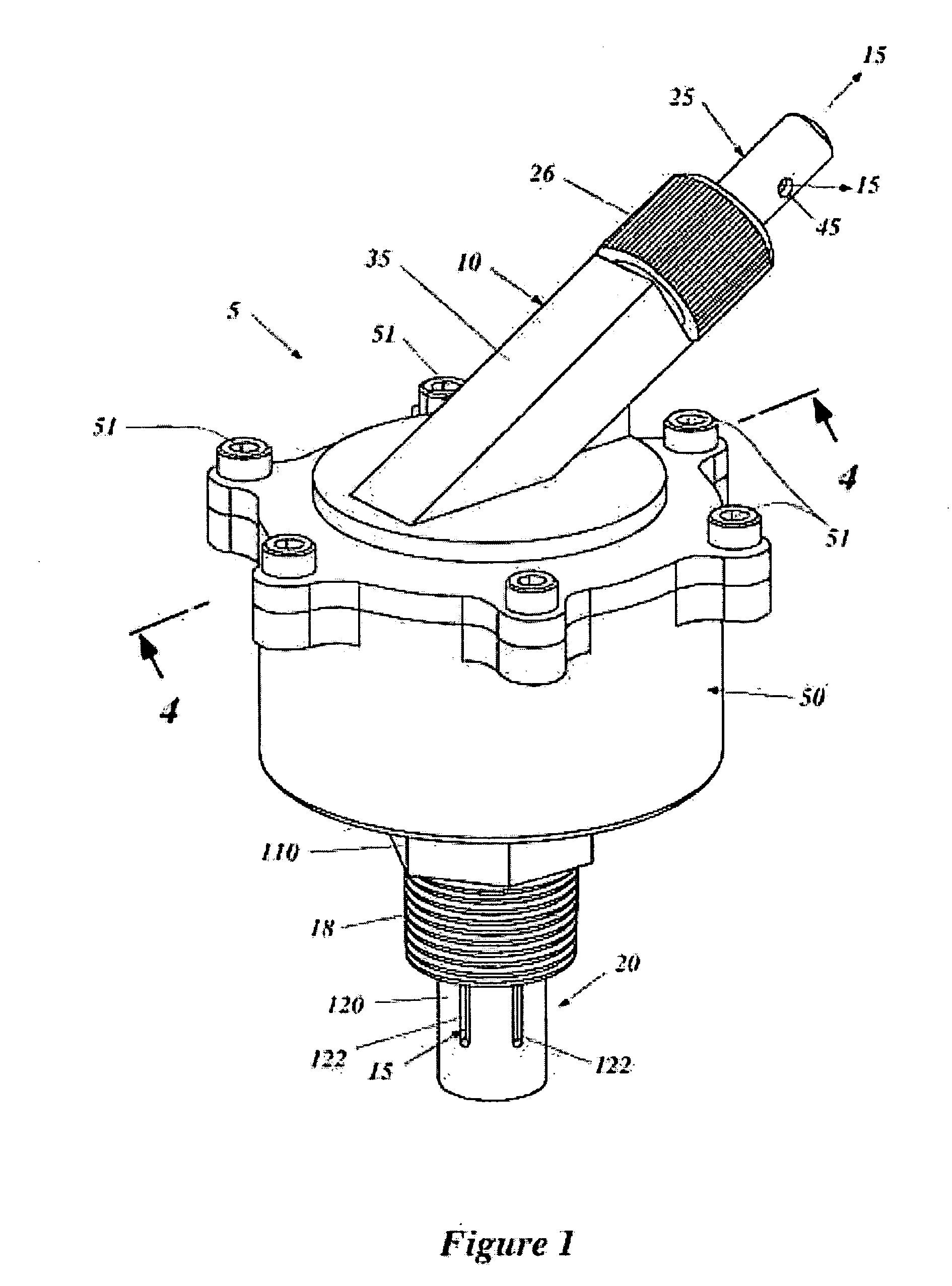
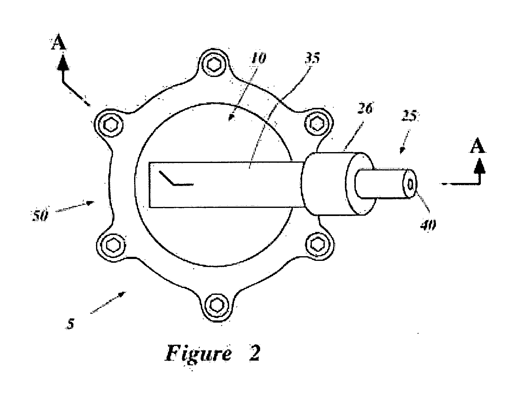
[0020] The figures, including FIG. 1, show one exemplary embodiment of a fluid distribution apparatus in accordance with the present invention. Persons of ordinary skill in the art will understand that various aspects of the invention can be practiced in a wide variety of other embodiments. In the embodiment illustrated, the various componen...


PUM


Abstract

The present invention is directed to a sprinkler apparatus and related methods for the distribution of fluid. The invention preferably includes a nozzle rotatably driven by a pressurized flow of fluid along a fluid path. The invention preferably includes a housing separating a magnetic drag coupling assembly from the fluid path. The coupling assembly preferably includes spaced apart magnets configured to exert an attractive force on each other to rotate one magnet in response to the rotation of the other magnet, and a resistive / drag force to oppose the continuous rotation of the nozzle. Pressure offsetting structures minimize or even neutralize the upward / downward forces that the flowing fluid otherwise would exert on the rotating shaft assembly.

Description

FIELD OF THE INVENTION [0001] The present invention relates generally to fluid distribution apparatus and methods, and more particularly, to a sprinkler. INCORPORATION BY REFERENCE [0002] The contents of each U.S. patent or other reference, if any, cited in this application, are hereby incorporated by reference. BACKGROUND OF THE INVENTION [0003] A wide variety of sprinklers are commercially available for controlling the distribution of water or other fluids in residential and industrial applications. Some of these sprinklers are mechanically complex, and include a relatively large number of interconnected parts to rotate and control the sprinkler nozzle. In some sprinklers, many of the moveable parts, including “control” parts, are in direct contact with fluid impurities or contaminants that may immediately, gradually, or eventually interfere with the sprinkler operation. In addition, some parts are subject to substantial friction or other wear caused by the water pressure itself a...

Claims


Application Information

Patent Timeline
IPC IPC(8): B05B15/06B05B15/10A01G25/06
CPCB05B3/005Y10S239/11B05B3/06B05B3/006
Inventor OLSON, DONALD O.
Owner NEPTUNE BENSON INC
Learn More