Motor rotor cooling with rotation heat pipes

a technology of heat pipes and rotors, which is applied in the direction of dynamo-electric machines, magnetic circuit rotating parts, magnetic circuit shape/form/construction, etc., can solve the problems of system downtime, maintenance, and motor performance degradation, and achieve the effect of reducing the size, facilitating the formation of liquid films, and not compromising the structural integrity of the rotor sha

Inactive Publication Date: 2006-03-30
BALDOR ELECTRIC COMPANY
View PDF27 Cites 174 Cited by
  • Summary
  • Abstract
  • Description
  • Claims
  • Application Information

AI Technical Summary

Benefits of technology

[0009] The present technique is designed to respond to such needs. A series of relatively small heat pipes are disposed in a rotor radially around the rotor center. For example, heat pipes may be positioned adjacent each aluminum conductor bar, a heat source within the rotor. The heat pipes, though individually placed as revolving heat pipes, exhibit behavior, in total, that approximates the favorable fluid-flow and heat-transfer behavior of a single larger rotating heat pipe. The advantageous behavior is due, in part, to a novel internal geometry of the heat pipes, which may include an arched inner surface which facilitates formation of a liquid film at higher rotating speeds. Further, unlike

Problems solved by technology

In general, excess heat left unabated may degrade the performance of the motor.
Worse yet, excess heat may contribute to any number of malfunctions, which may lead to system downtime and require maintenance.
Moreover, localized high operating temperatures (i.e., hotspots) sustained over time may lead to premature malfunction of the given location.
Undeniably, reduced efficiency and malfunctions are undesirable events that may lead to increased costs.
Moreover, motor applications have tended to be stator-limited with respect to operating temperature, and thus conventional approaches, such as shaft-mounted fan cooling, directed at the stator have generally been sufficient.
However, there are an increasing number of motor applications and designs where the rotor is prone to becoming excessively hot, and where cooling directed at the stator is not adequate in maintaining acceptable operating temperatures within the motor.
Such rotor temperature-limited applications include, for example, high-power and/or high-density motors in the mining, heating, ventilating, and cooling industries.
In the case of centrifuge mo

Method used


Image

  • Motor rotor cooling with rotation heat pipes
  • Motor rotor cooling with rotation heat pipes
  • Motor rotor cooling with rotation heat pipes

Examples


Embodiment Construction

[0030] As discussed in detail below, embodiments of the present technique provide for cooling of electric motors. Although the discussion regarding the present technique focuses on electric motors, it also affords benefits to a number of applications in which the cooling of a rotating element is a concern. Accordingly, the following discussion relates to exemplary embodiments of the present invention and, as such, should not be viewed as limiting the appended claims to the embodiments described.

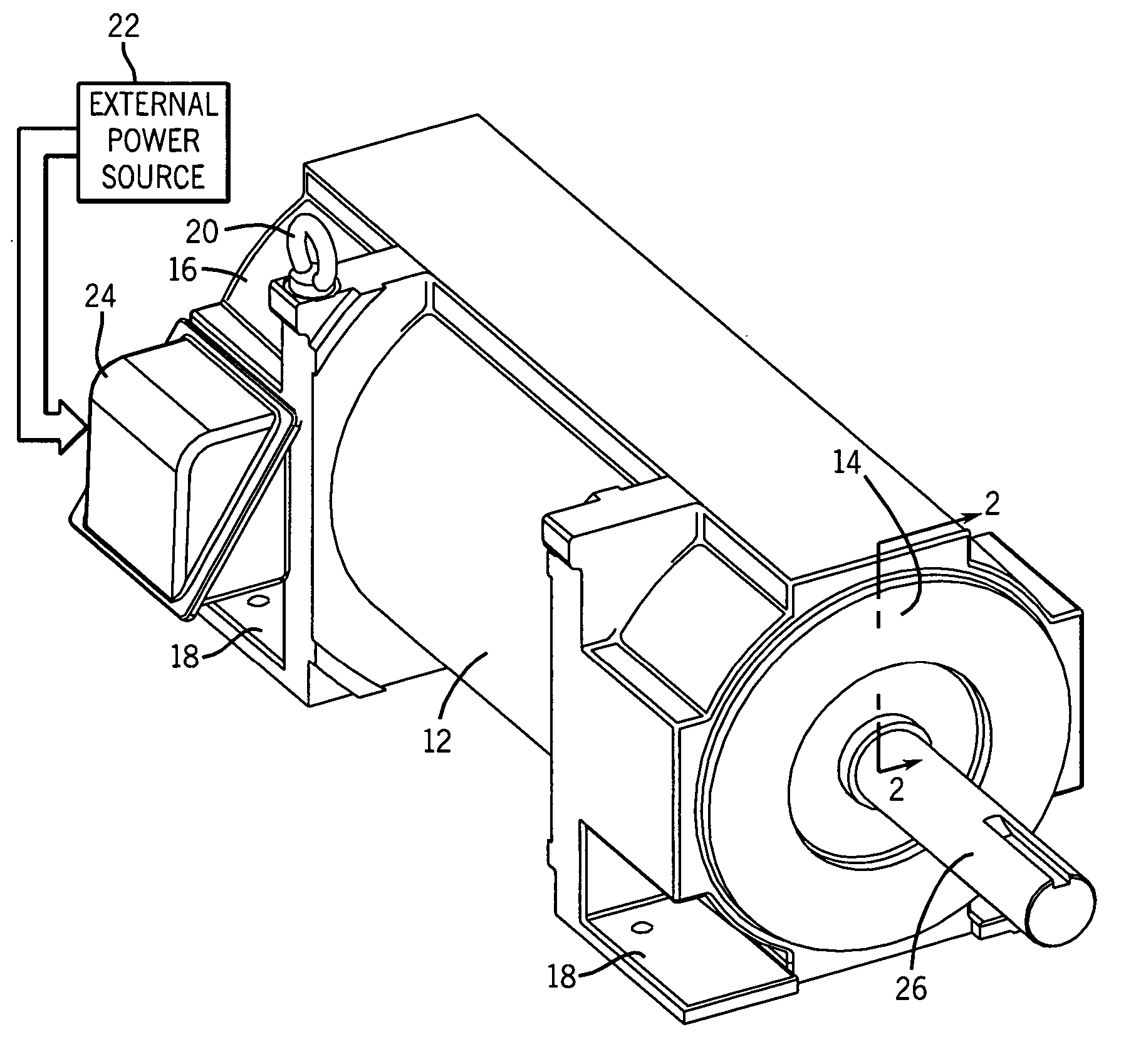
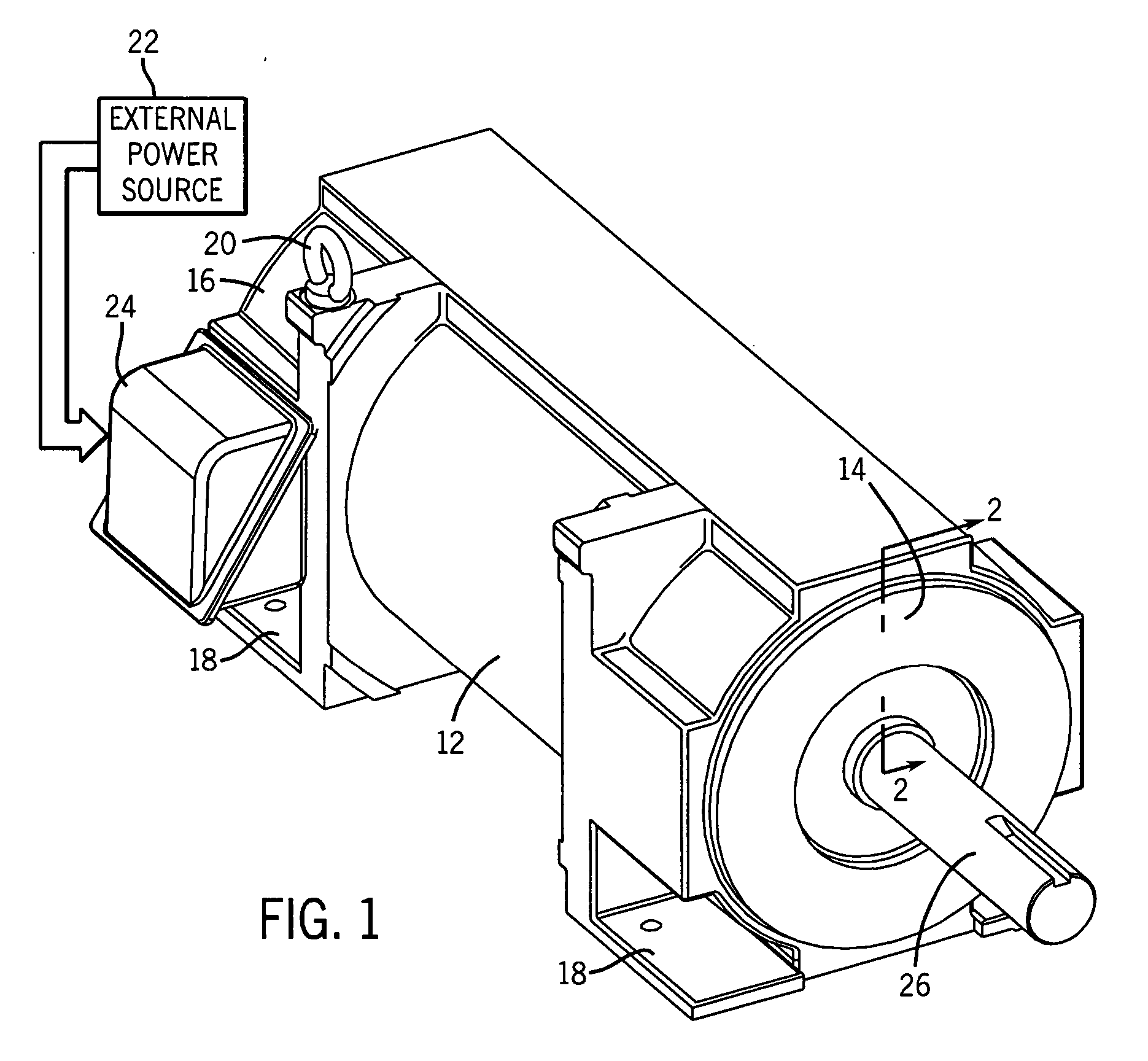
[0031] Turning to the drawings, FIG. 1 illustrates an exemplary electric motor 10. In the embodiment illustrated, the motor 10 comprises an induction motor housed in a National Electrical Manufacturers' Association (NEMA) motor housing. Industry associations, such as NEMA, develop particular standards and parameters for the construction of motor housings or enclosures. Of course, the present technique is applicable to a variety of motor housing constructions and is not limited to NEMA housin...


PUM


Abstract

A heat pipe is partially-filled with a liquid, such as water, and is used to transfer heat from a rotating element, such as a rotor, via phase change and internal recycle of the liquid. Several heat pipes may be disposed radially around the rotating axis of the rotating element. The heat pipes may have a curved inner surface with a curvature not corresponding to the central axis of the heat pipe and positioned opposite the rotating axis so to experience greater centrifugal forces, to advance formation of a liquid film to improve heat transfer. For a rotor, the heat pipes, though individually placed as revolving heat pipes, in total exhibit behavior that approximates the favorable heat-transfer behavior of a single larger rotating heat pipe, but with heat-transfer surface area dispersed throughout the rotor, and without compromising structural integrity of the rotor shaft.

Description

BACKGROUND [0001] The present invention relates to the use of heat pipes in the cooling of rotating elements such as rotors in electric motors. It should be emphasized that although the present discussion focuses on electric motors, the present technique affords benefits in heat removal in a number of systems employing rotating elements or components. [0002] Electric motors of various types are commonly found in industrial, commercial and consumer settings. In industry, motors are employed to drive various kinds of machinery, such as pumps, conveyors, compressors, fans and so forth, to mention only a few. These motors generally include a stator having a multiplicity of coils surrounding a rotor. The rotor is typically supported by bearings for rotation in a motor frame. When power is applied to the motor, an electromagnetic relationship between the stator and the rotor causes the rotor to rotate. The speed of rotation of the rotor may be specified at predetermined speeds, for exampl...

Claims


Application Information

Patent Timeline
IPC IPC(8): H02K9/20H02K9/00
CPCH02K9/20H02K9/225
Inventor DONG, QIMIN J.CHEN, CHUNG-LUNG C.L.
Owner BALDOR ELECTRIC COMPANY
Why Eureka
Try Eureka