Permanent magnet type generator
- Summary
- Abstract
- Description
- Claims
- Application Information
AI Technical Summary
Benefits of technology
Problems solved by technology
Method used
Image

Examples
Embodiment Construction
[0030] A preferred embodiment according to the present invention and some modifications of the preferred embodiment will be described with reference to the appended drawings.
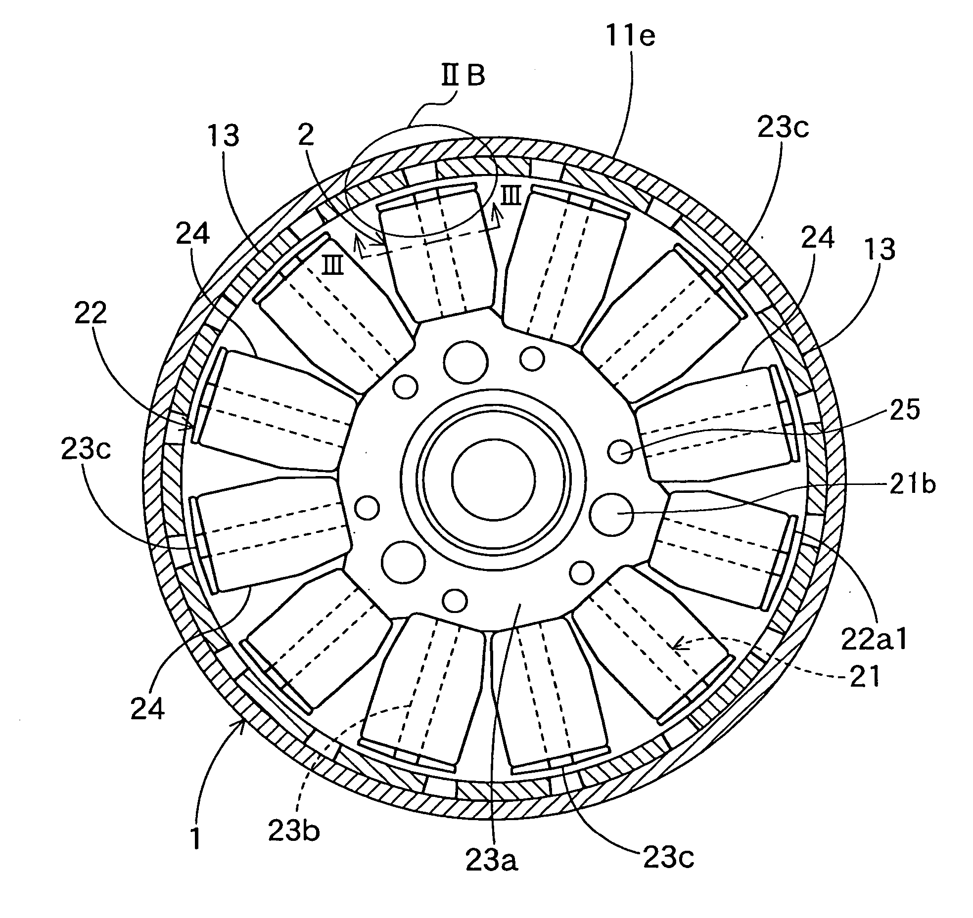
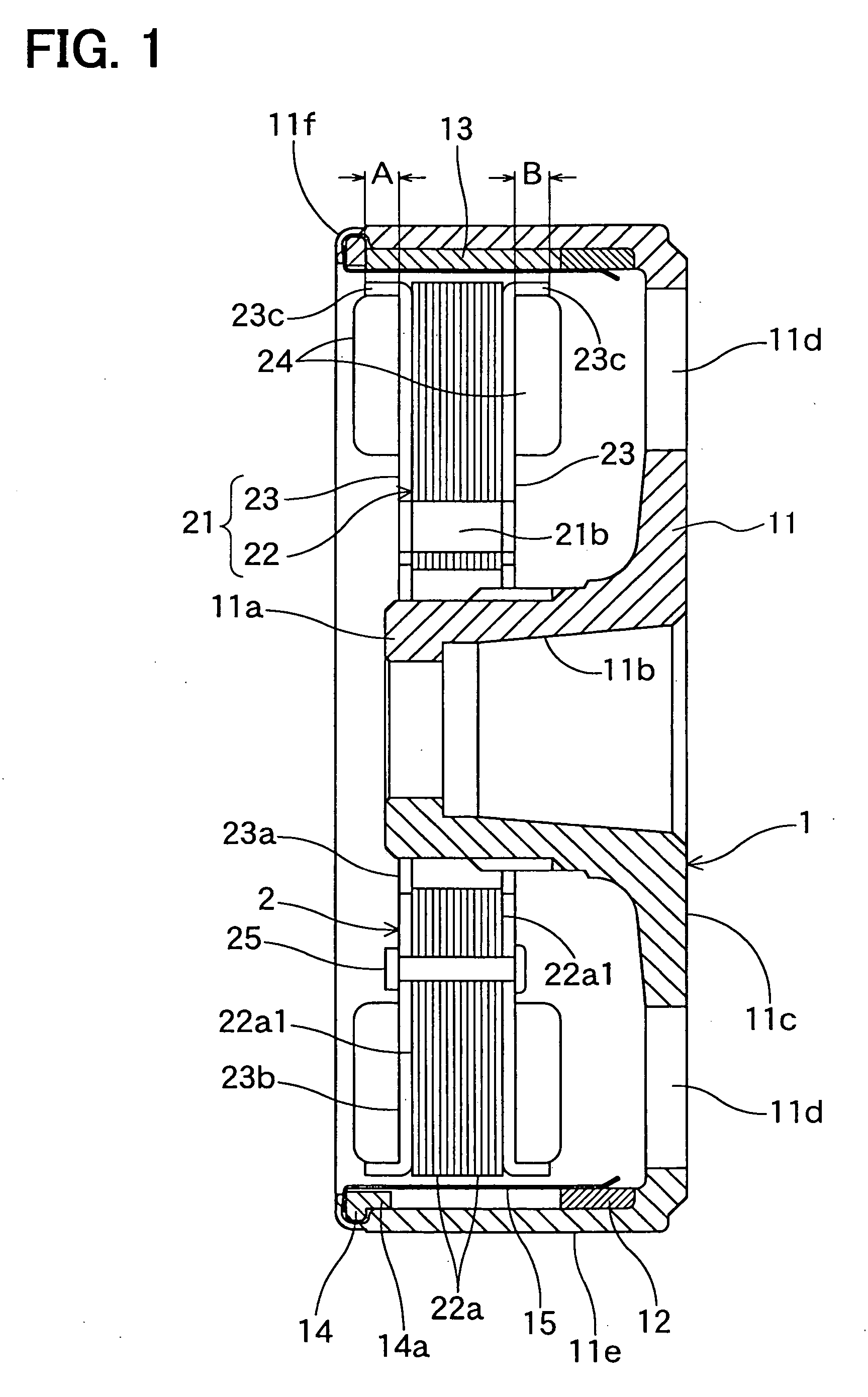
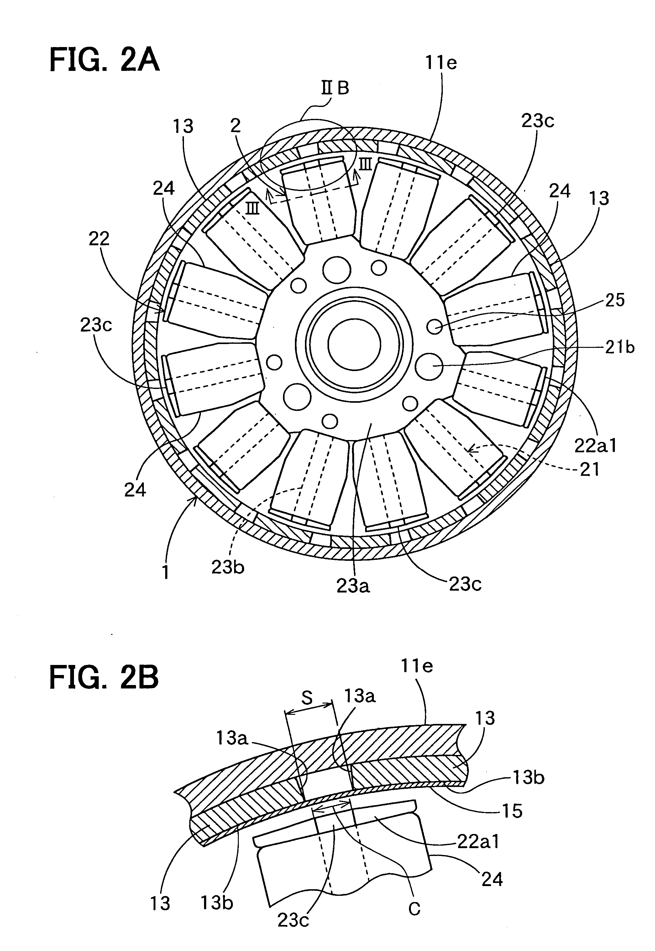
[0031] As shown in FIGS. 1 and 2A, a permanent magnet type generator includes a rotor 1 to be fixed to a crankshaft of an engine, a stator 2 disposed inside the rotor 1 and fixed to an engine cover. The rotor has 16 or 4n magnetic poles (n is a positive integer, e.g. 4), and the stator has 12 or 3n teeth.
[0032] The rotor 1 is comprised of a hot forged rotary magnetic member 11, a nonmagnetic ring spacer 12, 4n rare-earth permanent magnets 13, a ring-shaped magnet case 14 and a magnet protection ring 15.
[0033] The rotary magnetic member 11 includes a center boss 11a, an end surface 11c, a cylindrical yoke portion 11e and curled end portion 11f. The center boss 11a has a tapered surface so that the rotor 1 can be fixed to an engine crankshaft by a bolt via the tapered surface 11b. The end surface 11c has a plur...
PUM
 Abstract
Description
Claims
Application Information
 - Generate Ideas
- Intellectual Property
- Life Sciences
- Materials
- Tech Scout
- Unparalleled Data Quality
- Higher Quality Content
- 60% Fewer Hallucinations
Browse by: Latest US Patents, China's latest patents, Technical Efficacy Thesaurus, Application Domain, Technology Topic, Popular Technical Reports.
© 2025 PatSnap. All rights reserved.Legal|Privacy policy|Modern Slavery Act Transparency Statement|Sitemap|About US| Contact US: help@patsnap.com