Trapezoid ultra wide band patch antenna

a patch antenna and ultra wide band technology, applied in the direction of antenna details, antennas, basic electric elements, etc., can solve the problems of loss of feeding electric power, interference of uwb communication system with wlan frequency band, and difficulty in manufacturing monopole antennas, etc., and achieve the effect of low cos

Active Publication Date: 2006-03-30
UNILOC 2017 LLC
View PDF8 Cites 52 Cited by
  • Summary
  • Abstract
  • Description
  • Claims
  • Application Information

AI Technical Summary

Benefits of technology

[0008] It is, therefore, an object of the present invention to provide a micro-miniature, light weighted and low cost ultra wide antenna having an ultra wide band characteristics and a notch characteristics in 5 GHz WLAN band (5.15-5.35 GHz) by using a trapezoid patch, a matching stub, a CPW feed type and a rectangular slot.

Problems solved by technology

Therefore, the UWB communication system may generate an interference with the WLAN frequency band.
The via holes 30 may cause loss of feeding electric power and the monopole antenna is very difficult to be manufactured because of the complicated shape of the curved T shape patch 10.

Method used


Image

  • Trapezoid ultra wide band patch antenna
  • Trapezoid ultra wide band patch antenna
  • Trapezoid ultra wide band patch antenna

Examples


Embodiment Construction

[0022] Hereinafter, a trapezoid ultra wide band patch antenna in accordance with a preferred embodiment of the present invention will be described in more detail with reference to the accompanying drawings.

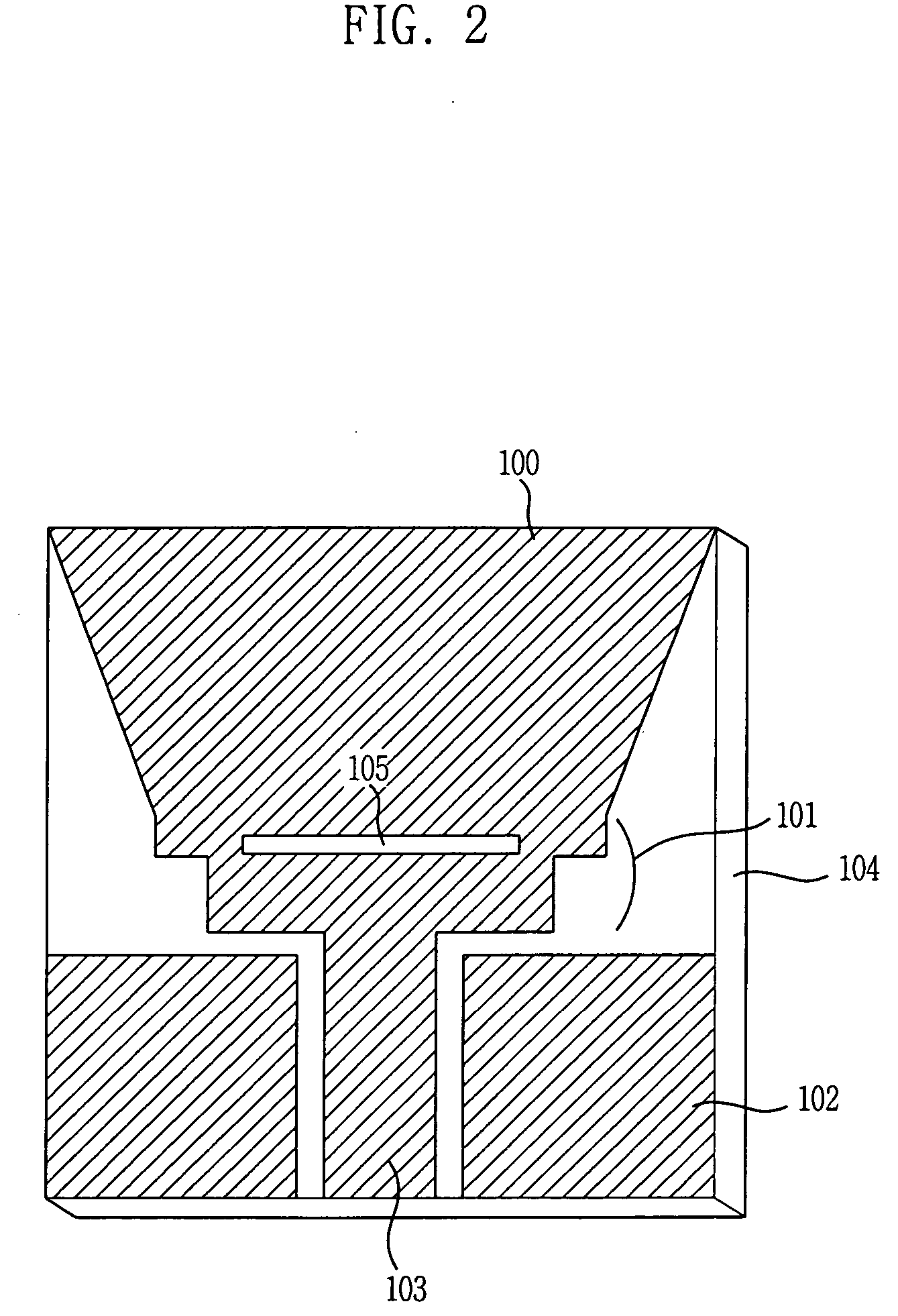
[0023]FIG. 2 is a diagram illustrating a trapezoid ultra wide band patch antenna in accordance with a preferred embodiment of the present invention.

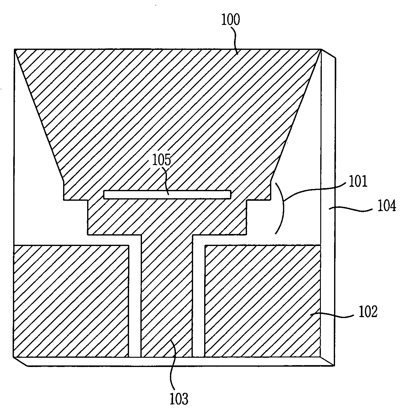
[0024] As shown in FIG. 2, the trapezoid ultra wide band patch antenna includes a trapezoid patch 100 having a rectangular slot 105, a matching stub 101, a ground 102, a coplanar waveguide (CPW) feeding line 103 and a dielectric substrate 104. That is, the trapezoid ultra wide band patch antenna is embodied by forming the trapezoid patch 100 on the dielectric substrate 104 and using the CPW feeding line 103 and the matching stub 101. The preferred embodiment of the present invention is embodied by using the trapezoid shape patch 100 having a size of 30×18 mm2, the ground 102 having a size of 13.35×10 mm2 and the dielectric substrate ...


PUM


Abstract

A micro-miniature, light weighted and low cost trapezoid ultra wide antenna having an ultra wide band characteristics and a notch characteristic in 5 GHz WLAN band (5.15-5.35 GHz) is disclosed. The trapezoid ultra wide antenna includes: a dielectric substrate; a trapezoid shaped patch formed at an upper end of a middle line on an upper side of the dielectric substrate; a feeding line formed at a bottom end of the middle line on the upper side of the dielectric substrate for feeding electric power to the trapezoid shaped patch; a matching stub formed between the trapezoid shaped patch and the feeding line for impedance matching between the trapezoid shaped patch and the feeding line; and a ground formed at a side of the feeding line on the upper side of the dielectric substrate.

Description

FIELD OF THE INVENTION [0001] The present invention relates to a trapezoid ultra wide band patch antenna; and, more particularly, to a coplanar waveguide (CPW)-fed micro-miniature ultra wide band patch antenna using a trapezoid shaped patch. DESCRIPTION OF RELATED ARTS [0002] An ultra wide band (UWB) communication system is a wireless communication technology developed by U.S. Department of Defense for a military purpose at 1960s. The UWB communication system provides fast transmission speed i.e., 500 Mbps to 1 Gbps, which is 10 times faster than a transmission speed of wireless local area network (WLAN) standard, IEEE 802.11a (54 Mbps). Also, the UWB communication system uses less electric power because the UWB communication systems use 10 s GHz of ultra wide frequency band. [0003] An ultra wide band (UWB) antenna is one of major factors of the UWB communication system. The UWB antenna requires a non-directional characteristic for all frequencies in target band, a small phase varia...

Claims


Application Information

Patent Timeline
Patent Type & Authority Applications(United States)
IPC IPC(8): H01Q1/38
CPCH01Q1/38H01Q9/0407H01Q9/0485H01Q5/25
Inventor PARK, JONG-KWEONPARK, BONG-HYUKLEE, SEUNG-SIKKIM, JAE-YOUNGCHOI, SANGSUNGLEE, SEOUNG-HUNLEE, JUNG-NAM
Owner UNILOC 2017 LLC
Why Eureka
Try Eureka