Liquid ejection apparatus and liquid tank

a liquid ejection and liquid tank technology, applied in printing and other directions, can solve the problems of inability to replace the filter alone, inability to extend and inability to replace the filter, etc., and achieve the effect of prolonging the working life of the filter

Inactive Publication Date: 2006-03-30
FUJIFILM CORP
View PDF5 Cites 68 Cited by
  • Summary
  • Abstract
  • Description
  • Claims
  • Application Information

AI Technical Summary

Benefits of technology

[0015] The present invention has been contrived in consideration of these circumstances, and it is an object thereof to provide a liquid ejection apparatus and liquid tank which enable reuse of a collected liquid without wasting the liquid, and which enable an extension of the working life of each filter.

Problems solved by technology

Therefore, if the ink containing such foreign matter is reused as is, the ink ejection nozzles become blocked, leading to defective ink ejection.
This filter is provided inside the ink cartridge, and hence it is impossible to replace the filter alone when the foreign matter blocks the filter.
In the apparatuses described in Japanese Patent Application Publication Nos. 2001-315357 and 2002-200771, ink is discharged together with the removed foreign matter, and therefore the ink consumption increases.
In the apparatus described in Japanese Patent Application Publication No. 2001-315358, the viscosity of the collected ink is reduced along the flow passage, and re-melting of the impurities that are separated by evaporation requires a large amount of time.
Therefore, this apparatus is inadequate.

Method used


Image

  • Liquid ejection apparatus and liquid tank
  • Liquid ejection apparatus and liquid tank
  • Liquid ejection apparatus and liquid tank

Examples


Embodiment Construction

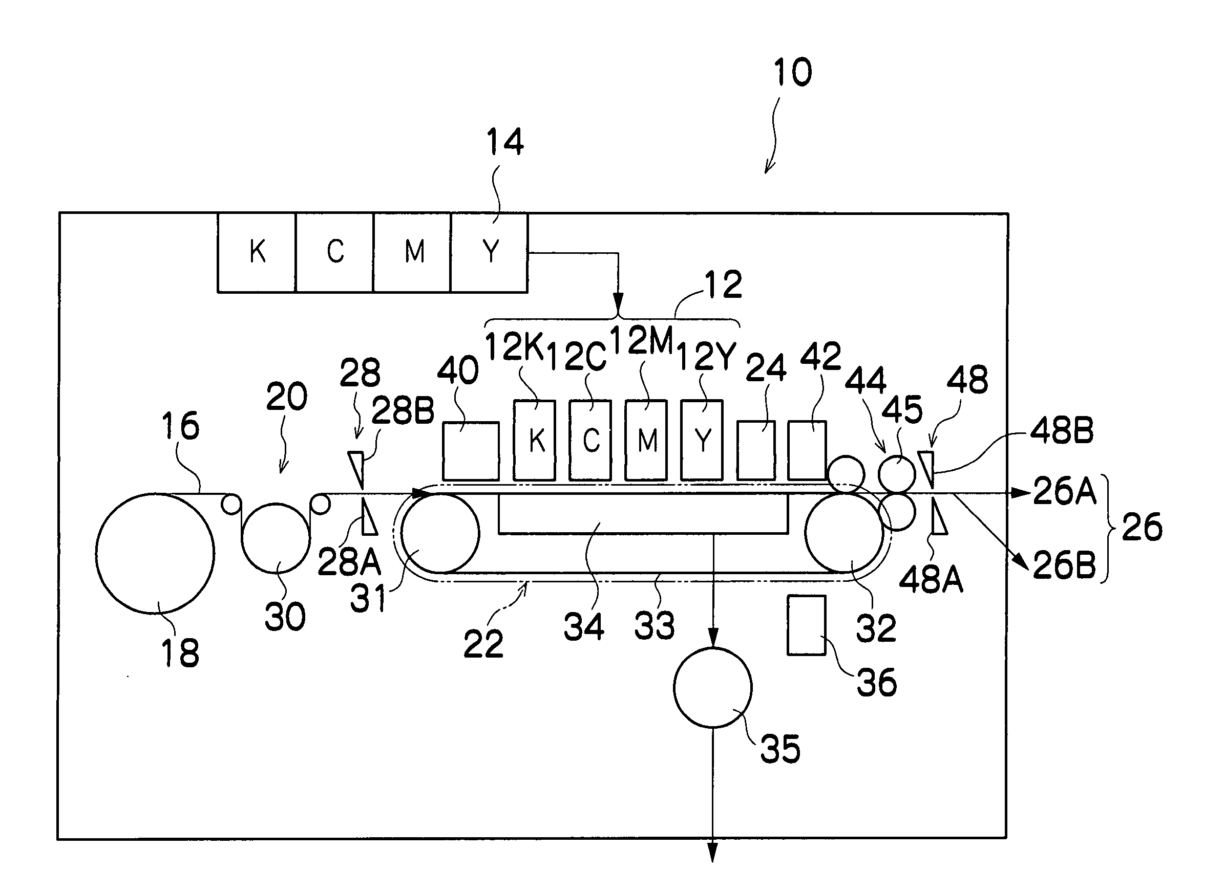
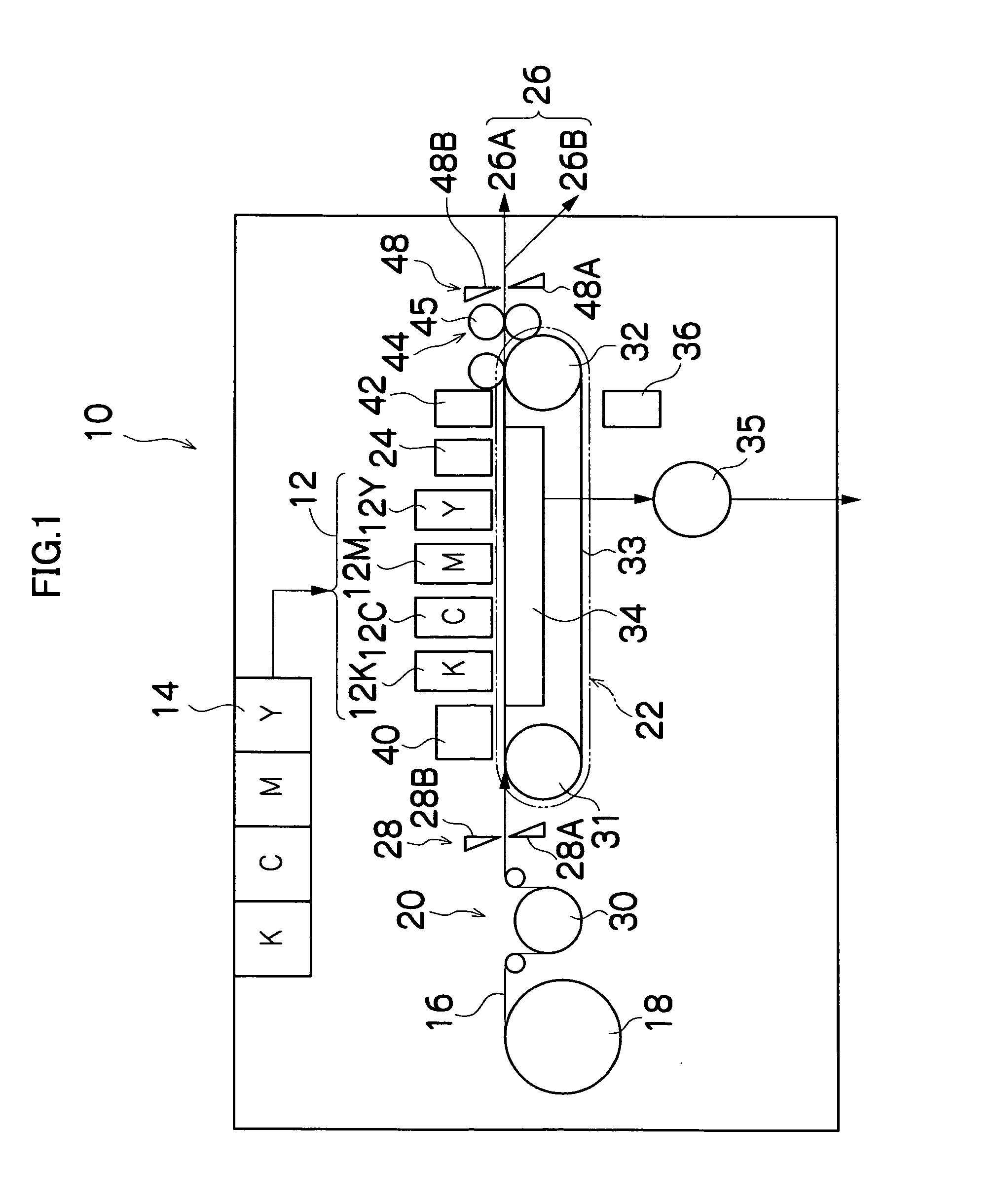
[0078]FIG. 1 is a general schematic drawing showing an outline of an embodiment of an inkjet recording apparatus to which the present invention is applied.

[0079] In FIG. 1, an inkjet recording apparatus 10 comprises a print unit 12 having a plurality of print heads 12K, 12C, 12M, 12Y provided for ink colors, an ink storing and loading unit 14 in which the ink supplied to the print heads 12K, 12C, 12M, 12Y is stored, a paper supply unit 18 which supplies recording paper 16, a decurling unit 20 which removes curls from the recording paper 16, a suction belt conveyance unit 22 disposed opposite a nozzle face (ink ejection face) of the print unit 12 for conveying the recording paper 16 while maintaining the flatness of the recording paper 16, a print determination unit 24 which reads printing results generated by the print unit 12, and a paper output unit 26 which outputs the printed recording paper (printed object) to the outside.

[0080] In FIG. 1, a magazine for rolled paper (continu...


PUM


Abstract

The liquid ejection apparatus comprises: a liquid ejection unit which ejects a liquid; a liquid storage unit which stores the liquid to be supplied to the liquid ejection unit; a plurality of flow passages through which the liquid flows; and a switching unit which holds a removable filter to trap foreign matter and switches a position of the filter so that the filter is connected to each of the plurality of flow passages in succession.

Description

BACKGROUND OF THE INVENTION [0001] 1. Field of the Invention [0002] The present invention relates to a liquid ejection apparatus and a liquid tank, and more particularly to a liquid ejection apparatus and liquid tank which remove foreign matter from a collected liquid so that the liquid can be reused. [0003] 2. Description of the Related Art [0004] When discarded ink is collected for reuse in an ink ejection apparatus comprising ink ejection nozzles, foreign matter such as viscous ink lumps and paper particles are typically contained in the discarded ink. Therefore, if the ink containing such foreign matter is reused as is, the ink ejection nozzles become blocked, leading to defective ink ejection. Hence, apparatuses comprising a filter for removing foreign matter from discarded ink have been proposed. [0005] Japanese Patent Application Publication No. 2-281960 discloses an apparatus formed with an ink collection chamber in the upper portion of an ink cartridge and an ink supply cha...

Claims


Application Information

Patent Timeline
Patent Type & Authority Applications(United States)
IPC IPC(8): B41J2/175
CPCB41J2/18B41J2/17563
Inventor TAKATSUKA, TSUTOMU
Owner FUJIFILM CORP
Why Eureka
Try Eureka