
Sheet post-process apparatus and processing tray

Inactive Publication Date: 2006-03-30
TOSHIBA TEC KK
View PDF35 Cites 12 Cited by
  • Summary
  • Abstract
  • Description
  • Claims
  • Application Information

AI Technical Summary

Benefits of technology

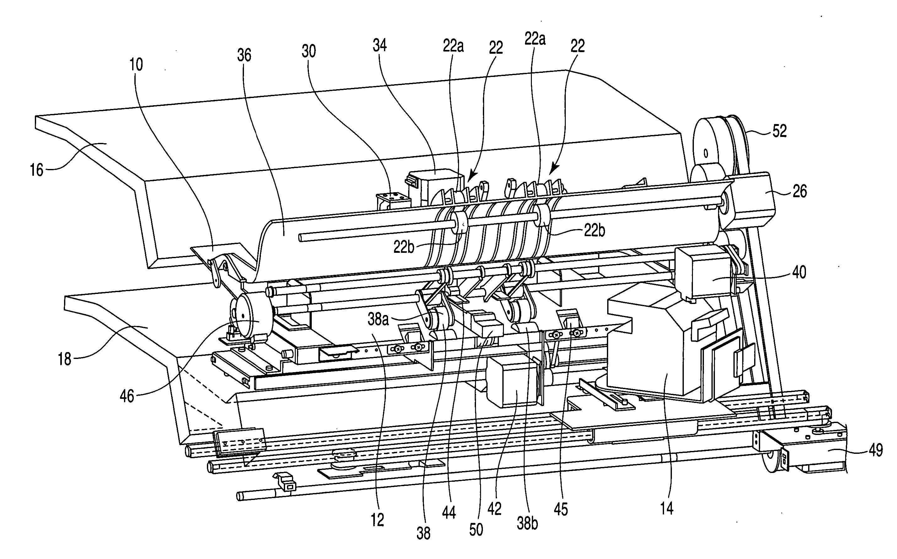
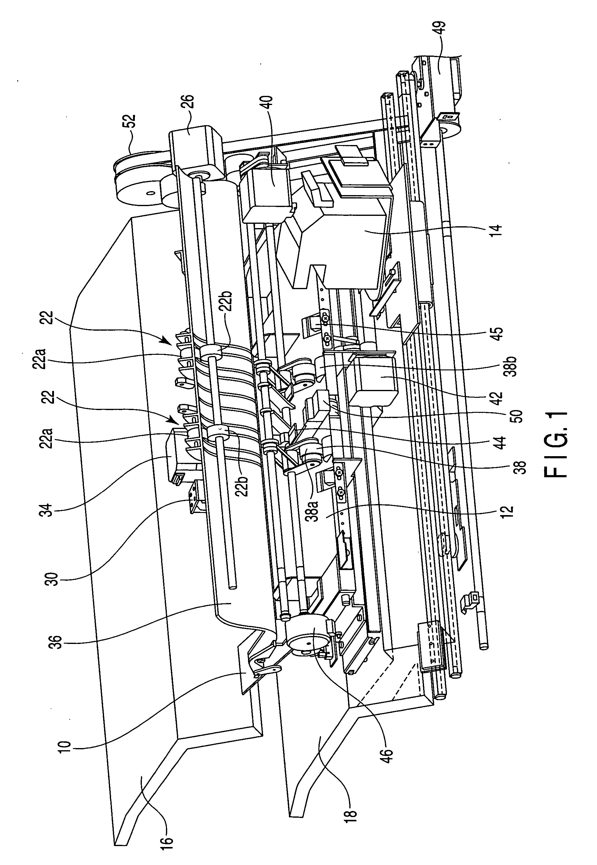
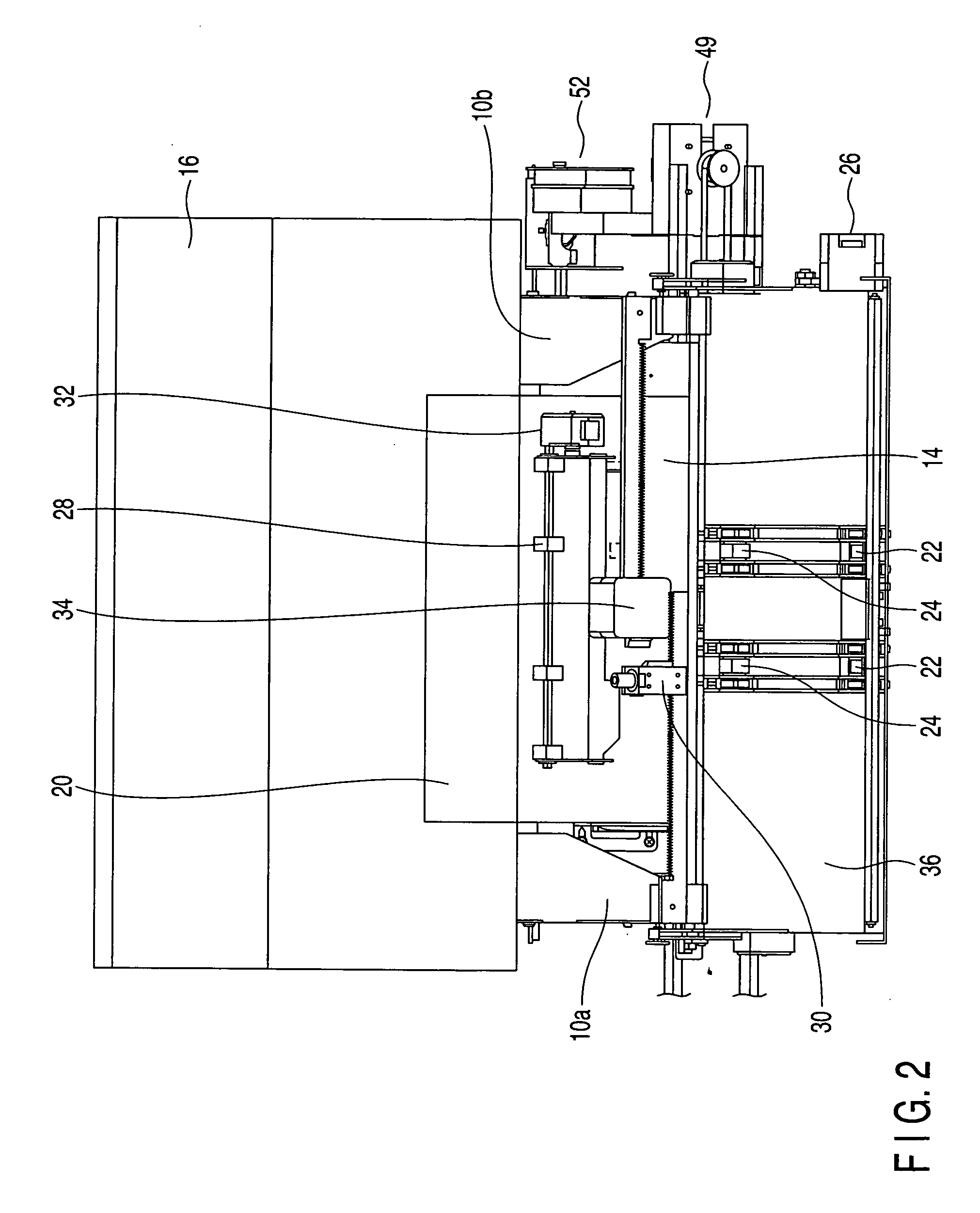
[0007] The Inventors proposes here that a waiting tray is newly allocated as a buffer mechanism at an upper stage of a processing tray. The waiting tray according to this proposal is allocated to be proximal to the upper stage of the processing tray, and a sheet transported from an image forming apparatus to the processing tray is temporarily retained here in a waiting mode. At a time point when retention in a waiting mode is released, that is, at a time point when staple processing of a bundle of sheets at the processing tray terminates, and then, the bundle of sheets is transported from the processing tray to a storage tray, the sheet is supported on a bottom face of the waiting tray. By opening this tray, the sheet is then dropped at the distal end side (upstream side when the sheet is transported to the waiting tray) to the processing tray. By using this waiting tray, equipment can be allocated with a simple mechanism without a need to increase a transport passage in length and providing a space. As a result, a post-process apparatus can be made compact. Moreover, it is possible to sent the sheets to the processing tray without any malfunction.
[0009] The present invention provides a post-process apparatus and a processing tray, the post-process apparatus capable of transporting a sheet from the processing tray to a storage tray without being cut into a push feed arm of a transport belt with a simple, inexpensive mechanism.
[0046] According to the present invention, inexpensive parts are mounted without using a specific transport belt, whereby a sheet can be reliably transported without being cut into a push feed arm of a transport belt. That is, a penetrating projection is allocated on a distal end push feed face of the arm by penetrating the belt, so that the sheet is not cut into a depth of the distal end push feed face by this penetrating projection. In addition, a proximal end of the penetrating is formed in a hook shape (hook shaped engagingly lock portion). Thus, the distal end push feed face is not floated from the belt, and the penetrating projection does not slip off from the belt. Moreover, this hook shaped engagingly lock portion is provided to be inclined in a downward direction while a belt traveling direction is defined as a reference. For example, this engagingly lock portion is inclined downwardly from an angle of 10 degrees to an angle of 30 degrees. Thus, even if the arm is placed at a portion along a radius of a pulley, a load does not increase, enabling natural rotation. Therefore, there is no danger that the arm slips off from the belt.

Problems solved by technology

However, in this case, there is a danger that, when a sheet dropped from the standby try is transported from the processing tray to the storage tray, the sheet distal end cuts into the sheet press feed face of a push feed arm for the sheet.

Method used


Image

  • Sheet post-process apparatus and processing tray
  • Sheet post-process apparatus and processing tray
  • Sheet post-process apparatus and processing tray

Examples


Embodiment Construction

[0070] Now, one embodiment of the present invention will be described here.

(General Description of Image Forming Apparatus)

[0071] A general description of an image forming apparatus (digital copying machine) allocated at a front stage of a post-process apparatus according to the present invention will be given with reference to FIG. 18. A manuscript placement base 112 is provided at an upper face of this apparatus. An auto document feeder 117 (hereinafter, referred to as an ADF) for automatically feeding a document D onto the manuscript placement base 112 is allocated on the manuscript placement base. The manuscript D is placed on the ADF, predetermined settings (such as the presence of absence of staple processing, how to carry out staple processing, the number of copies, or size of sheet to be copied, for example), and then, a copy start button is pressed. The manuscript D on the ADF is transported to a predetermined location of the manuscript placement base 112.

[0072] A scann...


PUM


Abstract

A processing tray comprises a transport belt which transports a sheet, and a push feed arm mounted to be projected onto a surface on a sheet transport side of the belt, the arm retaining a sheet distal end so that the sheet distal end can be pushed and fed, wherein the transport belt forms a through hole through which the push feed arm penetrates, and the push feed arm comprises a push feed face which pushes and feeds the sheet distal end, a penetrating projection portion which reaches a transport belt lower face from the push feed face through the through hole, and a hook shaped engagingly lock portion engagingly locked on the belt lower face after being bent from the penetrating projection portion to the transport belt traveling direction.

Description

CROSS-REFERENCE TO RELATED APPLICATIONS [0001] This application is based upon and claims the benefit of priority from prior Japanese Patent Application No. 2004-281780, filed Sep. 28, 2004, the entire contents of which are incorporated herein by reference. BACKGROUND OF THE INVENTION [0002] 1. Field of the Invention [0003] The present invention relates to an apparatus (finisher) for bundling sheets sent from an image forming apparatus and carrying out, for example, staple processing, and a processing tray for use in the post-process apparatus. [0004] 2. Description of the Related Art [0005] A post-process apparatus comprises: a processing tray for bundling sheets sent from an image forming apparatus, thereby carrying out, for example, staple processing, and ejecting the processed bundles of sheets; and a storage tray for holding the ejected bundles of sheets. A staple processing speed of the post-process apparatus is slow as compared with an image processing speed of the image formi...

Claims


Application Information

Patent Timeline
IPC IPC(8): G03B27/74
CPCG03B27/74B65H2801/27B65H31/3081
Inventor TERAO, YASUNOBUSUGIZAKI, YOSHIAKIIIJIMA, TOMOMIISE, TOKIHIKOTAKI, HIROYUKI
Owner TOSHIBA TEC KK
Learn More