Capacitively coupled power supply

a capacitive voltage divider and power supply technology, applied in the direction of electric variable regulation, process and machine control, instruments, etc., can solve the problems of large devices, bulky, and relatively high cos

Inactive Publication Date: 2006-03-30
INTERDIGITAL MADISON PATENT HLDG
View PDF10 Cites 11 Cited by
  • Summary
  • Abstract
  • Description
  • Claims
  • Application Information

AI Technical Summary

Benefits of technology

[0002] The present invention relates to power supplies in general, and more particularly, to generating a supply voltage using a capacitive voltage divider.

Problems solved by technology

While step down transformers have been used as power supplies, such devices tend to be large, bulky, and relatively expensive.

Method used


Image

  • Capacitively coupled power supply
  • Capacitively coupled power supply
  • Capacitively coupled power supply

Examples


Embodiment Construction

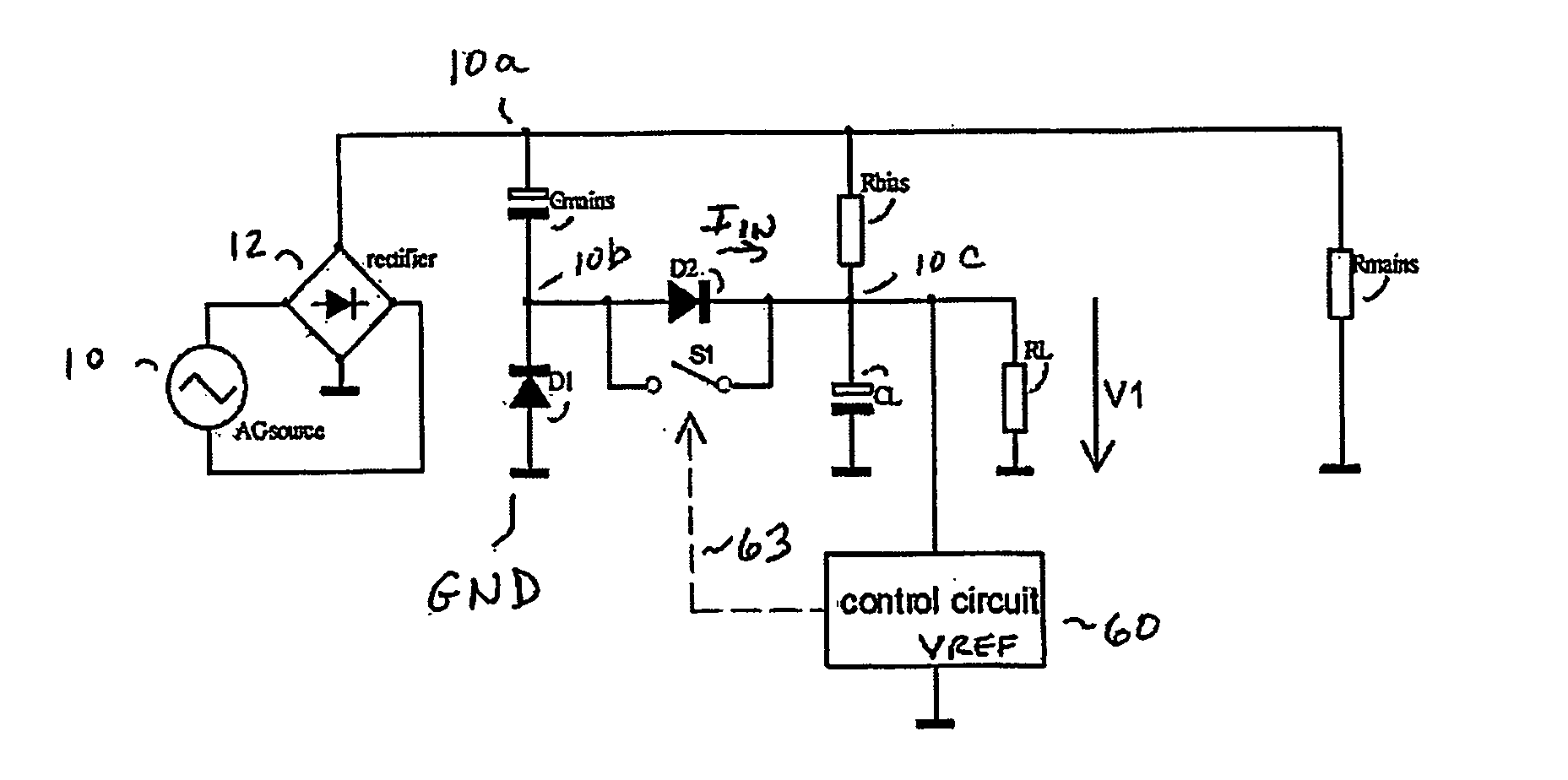
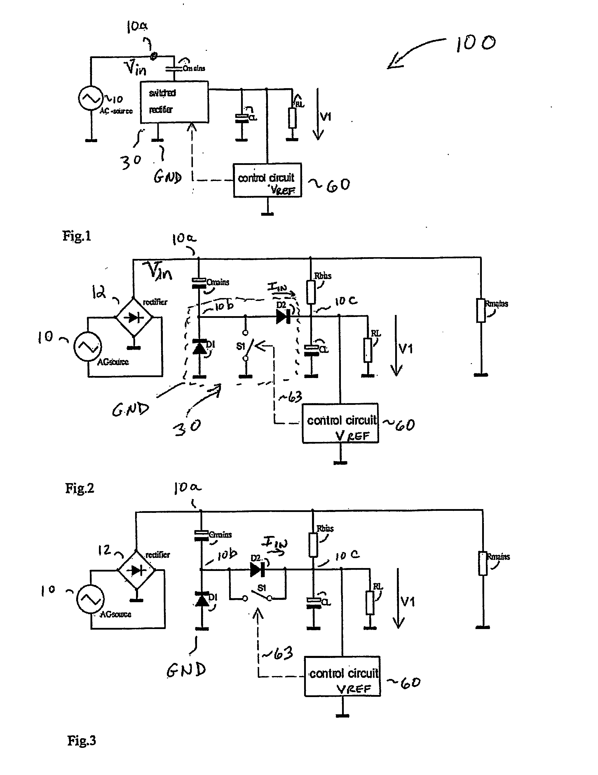
[0011]FIG. 1 is a block diagram illustrating a circuit 100 for generating a regulated supply voltage using a capacitive divider according to the general principles embodying the present invention. Throughout the drawings, like reference numerals are used to indicate like parts. The circuit 100 includes a source 10 of AC power applied at node 10a. A voltage or a current source may be used, however, in case of a mains application, it is understood that the source comprise an AC power line input A capacitive divider comprising capacitor Cmains and capacitor CL connected in series, is used to transform the input voltage (Vin) at node 10a to the desired output voltage level V1 across load device RL. Since the energy transfer is determined by the capacitor Cmains, a voltage source can automatically be considered as a current source.

[0012] Control circuit 60 coupled to the voltage divider arrangement measures the output voltage V1 and compares the measured output voltage with a reference ...


PUM


Abstract

A power supply comprises a pair of first and second capacitors forming a capacitive voltage divider. A source of a periodic input supply voltage is coupled to the capacitive voltage divider for producing in the second capacitor, from a portion of the periodic input supply voltage, a second supply voltage that is coupled to a load circuit. A switch is coupled to the second capacitor for selectively coupling the first capacitor to the second capacitor in a manner to regulate the second supply voltage.

Description

RELATED APPLICATIONS [0001] The present application claims priority under 35 U.S.C. § 119 of Provisional Patent Application Ser. No. 60 / 418,823 filed on Oct. 16, 2002.FIELD OF THE INVENTION [0002] The present invention relates to power supplies in general, and more particularly, to generating a supply voltage using a capacitive voltage divider. BACKGROUND OF THE INVENTION [0003] Power supplies serve the purpose of converting an input voltage into one or several output voltages. An AC power source may be used to provide an AC power line input, which gets converted to a DC regulated output voltage. Moreover, a power supply that produces a lower output voltage than that of the rectified main voltage power supply is generally needed in order to power small signal devices such as integrated circuit (IC) controllers and the like. Such power supplies should minimize losses occurring therein. While step down transformers have been used as power supplies, such devices tend to be large, bulky...

Claims


Application Information

Patent Timeline
Patent Type & Authority Applications(United States)
IPC IPC(8): H02M7/02H02M3/00H02M3/155H02M3/156H02M3/335
CPCH02M1/32H02M3/005Y02B70/1425H02M7/06H02M3/156Y02B70/10H02M1/096H02M7/217
Inventor WEBER, RUDOLF
Owner INTERDIGITAL MADISON PATENT HLDG
Why Eureka
Try Eureka