
Method and system for shared backup allocation in networks based on partial information

a technology of partial information and network backup, applied in the field of communication networks, can solve the problems algorithm does not provide any guarantee on the quality of solutions, and is difficult to achieve fast recovery at the expense of low network utilization ra

Inactive Publication Date: 2006-03-30
WSOU INVESTMENTS LLC
View PDF7 Cites 37 Cited by
  • Summary
  • Abstract
  • Description
  • Claims
  • Application Information

AI Technical Summary

Problems solved by technology

However, representing this information can be quadratic in the number of links, making it impractical in large networks.
However, these algorithms do not provide any guarantee on the quality of the solutions.
However, this fast recovery is obtained at the expense of low network utilization, since more than twice the required network resources are allocated to each connection.
Consequently, the routing algorithm cannot exploit resource sharing and the amount of allocated resources is the same as in the case of 1+1 protection.
However, in large networks this is not practical due to the large amount of required information.
However, the proposed schemes do not provide any guarantee on the quality of the calculated solutions.

Method used

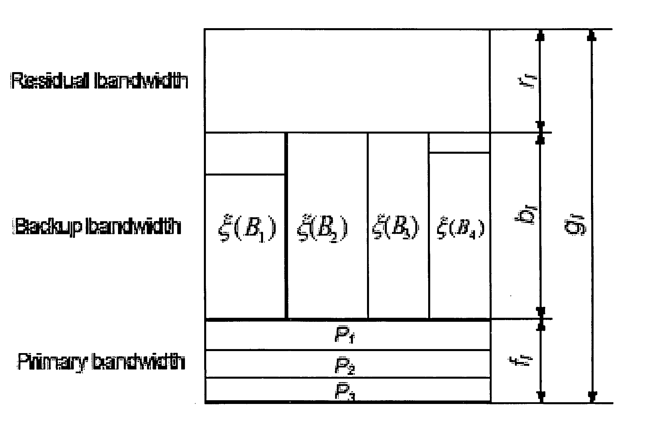
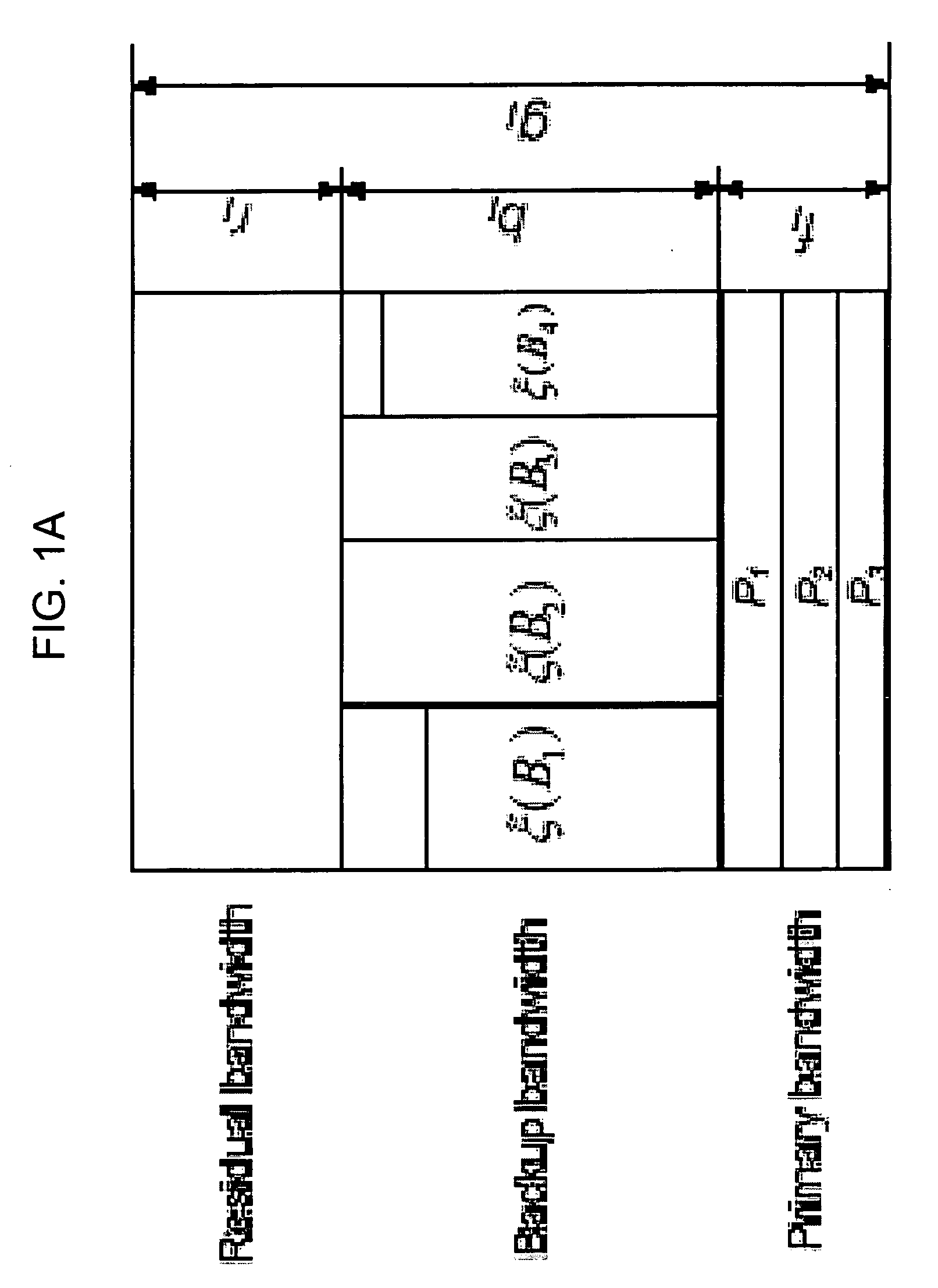

Image

  • Method and system for shared backup allocation in networks based on partial information
  • Method and system for shared backup allocation in networks based on partial information
  • Method and system for shared backup allocation in networks based on partial information

Examples


example 3

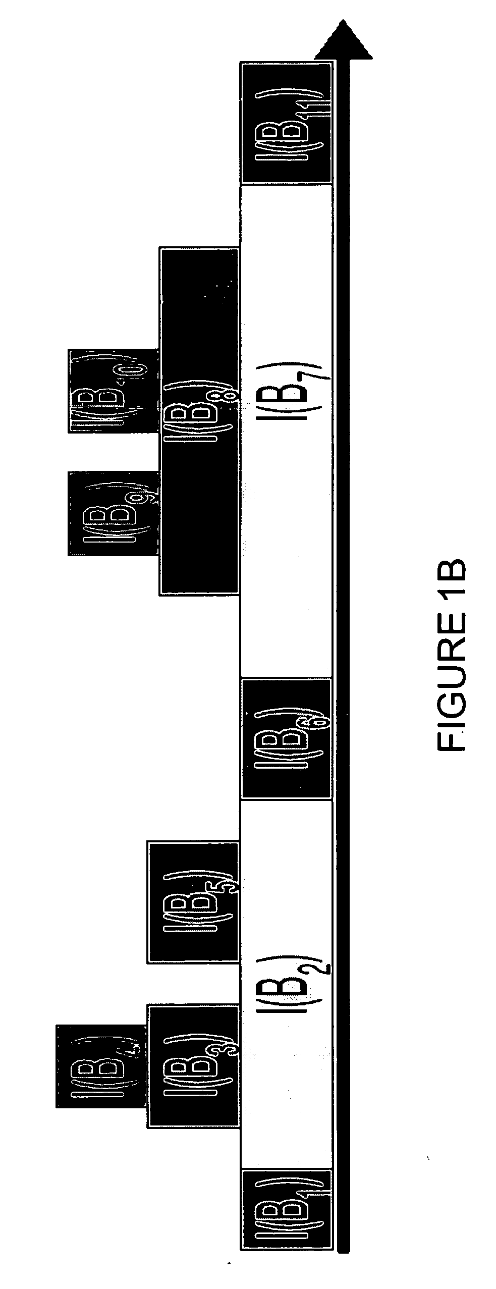
[0092]FIG. 1B demonstrates the inner domains of bridges in R. Bridges B2, B3, B4 and B5 form a superbridge, which, in turn, includes a superbridge formed by bridges B3 and B4.

[0093] The superbridge consists of the leading bridge BH and the set of bridges (Possibly even superbridges) nested within it. e.g., in FIG. 2A, BH is a leading bridge (outer bridge). There is a nested superbridge between v1 and v4, because it has bridges, with nesting. The bridge v1 to v4 is a leading bridge, with the bridge v2 to v3 nested therein.

[0094] Dynamic Programming Algorithm

[0095] Problem BS* has an optimal substructure property. This property can be used in order to establish a dynamic programming algorithm for this problem, suitable for an automated implementation on a computer processor. Given an instance (G,{circumflex over (P)},d) of Problem BS*, the algorithm determines the optimal superbridges for protecting every interval I of {circumflex over (P)}, beginning with intervals of length 1, th...

example 4

[0101]FIG. 2A depicts an example of a superbridge of an interval I={s(I)=v0,v1 . . . ,t(I)}=v7. Here, the leading bridge BH protects all links l ∈ I with fl≦3.

[0102] The above process determines the optimal superbridge for each interval I of P. The optimum solution R is partitioned into a set of superbridges, each protecting an interval I of {circumflex over (P)}. Thus, R can either include a single superbridge that protects the entire path {circumflex over (P)} or comprises several superbridges. Note that the minimum cost of a superbridge that protects the entire path {circumflex over (P)} is already known. In order to compute the set of superbridges that protects each link l ∈ {circumflex over (P)} of minimum total cost, a procedure such as Procedure FIND is invoked for {circumflex over (P)} and ζ=0. A formal description of the algorithm appears in Tables 1 to 3.

[0103] The above-described process may be implemented on a variety of computer platforms in any of a variety of progra...


PUM


Abstract

A method comprises allocating a respective restoration path to protect each of a plurality of primary paths in a network. Each primary path has a plurality of nodes and at least two subpaths connecting the nodes of the primary path. Each restoration path includes at least one link. Each link protects at least one of the subpaths of the primary path. Each of the subpaths of the primary path is protected. None of the links in the restoration path is included in the corresponding primary path. At least one of the links is shared among at least two restoration paths corresponding to at least two of the primary paths.

Description

FIELD OF THE INVENTION [0001] The present invention relates to communications networks generally, and more specifically to methods and systems for designing and implementing primary and backup link topologies. BACKGROUND [0002] Modern communication networks are required to provide Quality of Service (QoS) assurance and fault resilience, while maximizing their utilization. This prompts the need for new dynamic restorable routing algorithms that exploit restoration resource sharing for achieving these goals. The best possible sharing can be obtained when the routing algorithms have complete information of all primary and restoration paths. However, representing this information can be quadratic in the number of links, making it impractical in large networks. Recently, M. Kodialam and T. V. Lakshman, “Restorable Dynamic Quality of Service Routing,” IEEE Communications Magazine, vol. 40, no. 6, pp. 72-81, 2002, also described in U.S. Pat. No. 6,584,071, (both of which are incorporated b...

Claims


Application Information

Patent Timeline
IPC IPC(8): H04L12/28H04L12/26
CPCH04L41/0663H04L41/0896H04L45/28H04L45/123H04L45/22H04L45/00H04L45/247
Inventor BEJERANO, YIGALNAOR, JOSEPH SEFFISPRINTSON, ALEXANDER
Owner WSOU INVESTMENTS LLC
Learn More