Image forming apparatus

a technology of forming apparatus and forming chamber, which is applied in the direction of electrographic process apparatus, instruments, optics, etc., can solve the problems of so-called background fog, and achieve the effect of preventing the occurrence of mixing of colors or background fog, high agitation capability, and high agitation capability

Active Publication Date: 2006-03-30
BROTHER KOGYO KK
View PDF3 Cites 7 Cited by
  • Summary
  • Abstract
  • Description
  • Claims
  • Application Information

AI Technical Summary

Benefits of technology

[0037] For this reason, according to this configuration, the development unit that is last in sequence of formation of a developing-agent image is made higher than the development unit that is first in sequence of formation of a developing-agent image, in view of the agitation capability of agitation member; and each of the development units is greater than an immediately-preceding development unit in sequence of formation of a developing-agent image in view of agitation capability (the agitation capability of each development unit is made equal to or in excess of the agitation capability of an immediately-preceding development unit). Accordingly, in relation to the developing-agent carrier which is second to last in sequence of formation of a developing-agent image, the development unit having high agitation capability efficiently disperses the reversely-transferred developing agent in the developing-image storage chamber by the development unit having high agitation capability, thereby preventing occurrence of mixing of colors or background fog.
[0038] In another conceivable configuration, the agitation capabilities of all of the development units are improved. However, such a configuration entails an increase in drive load of an agitation mechanism for all of the development units. In association with the increase in drive load, a larger drive source is required, which may in turn lead to n increase in cost and the size of an apparatus. Therefore, the configuration for improving the agitation capability of one of the plurality of development units is employed.

Problems solved by technology

The developing agent whose polarity has been inverted adheres to an area outside the region of the image carrier for an electrostatic latent image, thereby causing so-called background fog.

Method used


Image

  • Image forming apparatus
  • Image forming apparatus
  • Image forming apparatus

Examples


first embodiment

[0051] A first embodiment of the present invention will be described with reference to FIGS. 1 to 4.

[0052] 1. Configuration of a color laser printer

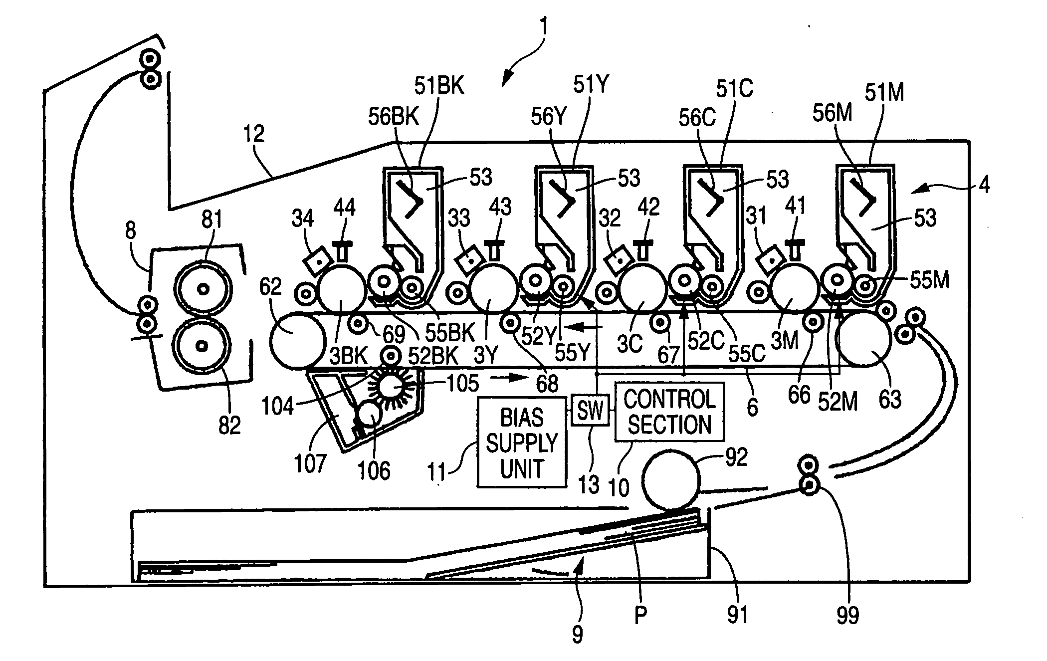
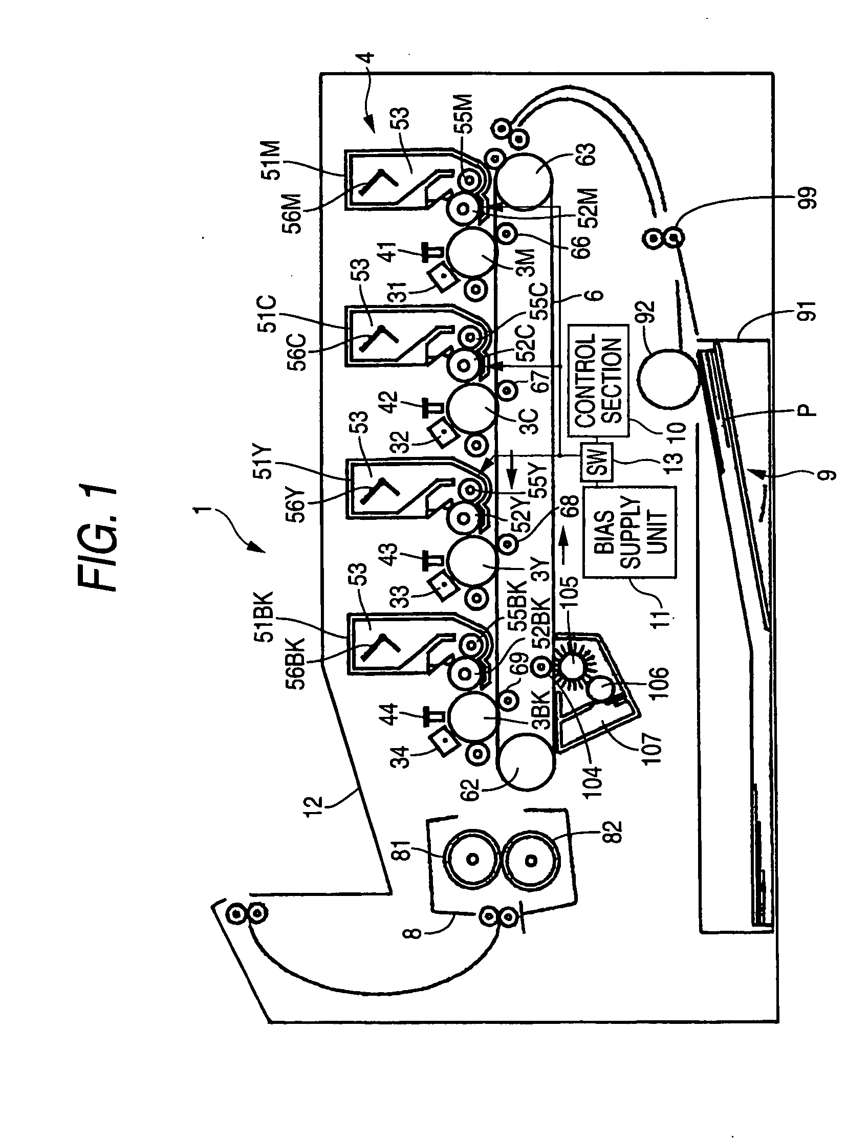
[0053]FIG. 1 is a side cross-sectional view showing a diagrammatic configuration of a color laser printer 1 serving as an image forming apparatus to which the present invention is applied. As shown in FIG. 1, the color laser printer 1 (image forming apparatus) of the present embodiment includes a visible-image-forming section 4; a paper transport belt 6; a fixing section 8; a paper-feeding section 9; a stacker 12; a control section 10; and a bias supply unit 11. Toner images of four colors (images formed by use of a developing agent) corresponding to the image data input from the outside are sequentially formed on the paper P (a transfer-target material, a recording medium), whereby a multicolor image is formed.

[0054] (1) Visible-Image-Forming Section

[0055] The visible-image-forming section 4 includes four development units 51 (51M, ...

second embodiment

[0114]FIGS. 5 and 6 show a second embodiment (corresponding to inventions of claims 2 and 7). A difference between the first and second embodiments lies in the method for improving recovery capability and a method for determining whether or not the recovery capability improvement operation is to be performed. In other respects, the second embodiment is analogous to the first embodiment. Consequently, those reference numerals which are the same as those of the first embodiment are assigned to elements of the second embodiment, and their repeated explanations are omitted. Only a difference between the first and second embodiments will now be described.

[0115] In the embodiment, recovery capability is changed by changing a nip width N (a contact width of the feeding roller 55 in the rotational direction thereof) where the development roller 52 and the feeding roller 55 come in contact with each other. Specifically, as shown in FIG. 5, the rotary shafts 55a of the respective feeding rol...

third embodiment

[0124]FIG. 8 is aside cross-sectional view showing a diagrammatic configuration of a color laser printer 1 according to a third embodiment.

[0125] In this embodiment, bias voltages (400 V) of essentially the same levels are applied to the respective development rollers 52 and the respective feeding rollers 55. Accordingly, the respective feeding rollers 55 supply the toner held in the toner hopper 54 to the development rollers 52 in the nip sections, as well as functioning as the recovery unit which scrape the toner (the waste developing agent) adhering to the surface of the development roller 52 to thus recover the toner into the toner hopper 54.

[0126] In the embodiment, the respective feeding rollers 55 are columnar bodies of the same diameter. The rotational speed (the number of revolutions per unit time) of the feeding roller BK of the fourth development unit 51BK is faster than the rotational speeds of the feeding rollers 55Y to 55C of the first to third development units 51Y ...


PUM


Abstract

An image forming apparatus includes: a plurality of development units having developing-agent carriers which are provided in correspondence to three or more developing agents, and developing electrostatic latent images on surfaces of image carriers to form developing-agent images on the image carriers; and a recovery unit that recovers the developing agent adhering to the developing-agent carrier during non-development operation. The recovery unit is provided for at least the development unit other than the development unit that transfers the developing-agent image first in sequence among the plurality of development units. When one of the plurality of development units performs development by the developing agent whose charge capability is higher than that of the developing agent of the development unit that transfers the developing-agent image later in sequence, the recovery unit starts recovery of the developing agent or performs recovery operation for improving recovery capability of the developing agent.

Description

BACKGROUND OF THE INVENTION [0001] 1. Field of the Invention [0002] The present invention relates to an image forming apparatus which forms a multicolor image by transferring, onto a material on which images are to be transferred (hereinafter called a “transfer-target material”), images sequentially formed on image carriers through use of a developing agent by means of a plurality of development units. [0003] 2. Description of the Related Art [0004] In a hitherto-known image forming apparatus, images are sequentially formed, by use of a developing agent, on surfaces of a plurality of image carriers (a single image carrier in the case of a so-called four-cycle system), on each of which an electrostatic latent image is formed, by use of a plurality of development units. These images formed by use of the developing agent (such images will be called “developing-agent images” throughout the specification) are sequentially transferred onto a transfer-target material, such as paper or an i...

Claims


Application Information

Patent Timeline
Patent Type & Authority Applications(United States)
IPC IPC(8): G03G15/08
CPCG03G15/0121G03G2215/0122G03G2215/0119G03G21/0064
Inventor HATTORI, TOMOAKINAKAYA, YUKIKO
Owner BROTHER KOGYO KK
Why Eureka
Try Eureka