Hydraulic machine

a hydraulic machine and toothed technology, applied in the direction of engine lubrication, rotary or oscillating piston engines, piston engines, etc., can solve the problems of increased risk of wear, increased wear, and inability to reach the clearance area, so as to reduce the risk of wear, increase the surface pressure, and the effect of extremely short transition area

Inactive Publication Date: 2006-03-30
SAUER DANFOSS NORDBERG
View PDF10 Cites 18 Cited by
  • Summary
  • Abstract
  • Description
  • Claims
  • Application Information

AI Technical Summary

Benefits of technology

[0010] It is particularly advantageous that in the axial direction the transition face has a convex, particularly elliptic, or a straight shape. Both embodiments cause that no additional edge occurs, at which an increased surface pressure could again occur. With a convex shape of the transition face, an “edge” does strictly speaking not exist any more, as here the transition face extends practically in a “rounded” manner into the circumferential surface. In this case, the border between the transition face and the front wall or the end wall, respectively, is regarded as edge.
[0011] Preferably, the edge has, in the axial direction, a distance in the range from 1 to 3 mm to the circumferential surface. Thus, the transition area is extremely short. This has the advantageous effect that “leakages” practically do not exist.
[0012] It is also advantageous that, at least at the largest depth of the clearance, the edge is offset radially inwards in the range from 0.01 to 0.03 mm in relation to the circumferential surface. As mentioned briefly above, the offsetting of the edge radially inwards is extremely small. It has the size of one to a few hundredth of a millimetre. This has the advantage that the compressive stress or the surface load can also extend into the transition area. Otherwise, there is a risk that the wear problem will simply be displaced axially outwards.
[0013] Preferably, a material share between the circumferential surface and the edge is removed by electrolyte-mechanical trimming. This is a relatively simple opportunity of producing a smooth transition between the clearance and the circumferential surface. Only very little material is removed. With the electrolyte-mechanical trimming it is possible to remove this material during the manufacturing of gear wheel or toothed ring, as the electrolyte-mechanical trimming does not take much time. Finally, also grinding tracks or tracks of another purely mechanical material removal are avoided, which could otherwise have an interfering effect on the operation of the hydraulic machine.
[0014] Preferably, the tooth flank has, at least on one front side, an end edge, which ends inwardly offset in the radial direction in relation to the circumferential surface. In fact, the same problem exists at the front side than at the transition between the circumferential surface and the clearance. Therefore, a transition face can also be provided at the front side, said transition face having a convex, particularly an elliptic, or a straight shape. This will also reduce the risk of wear at the control system. In a similar manner than with the clearance, the edge can have a distance in the radial direction of 1 to 3 mm to the circumferential surface and can be offset radially inwards by a few hundredth of a millimetre.
[0015] It is particularly preferred that each of the two front sides has an end edge, which ends offset radially inwards in relation to the circumferential surface. When, thus, both front sides and both axial ends of the clearance do not immediately extend into the circumferential surface by way of an edge, but his edge is slightly offset radially inwards, so that a transition face occurs, the wear problems are drastically reduced.

Problems solved by technology

While, between the clearance and the front side of the gear wheel or the toothed ring, respectively, the active force can be distributed on a relatively large area, this is not possible in the vicinity of the clearance.
It is now assumed that this increased surface pressing is causing the increased wear.
Exactly here, however, the increased risk of wear exists.

Method used


Image

  • Hydraulic machine
  • Hydraulic machine
  • Hydraulic machine

Examples


Embodiment Construction

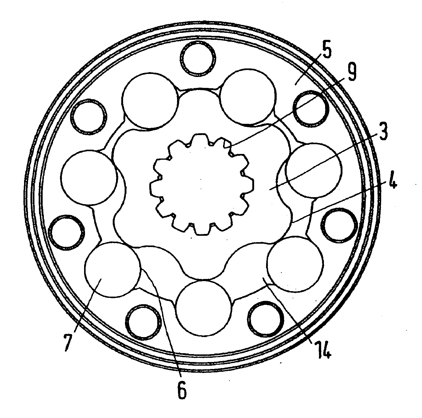
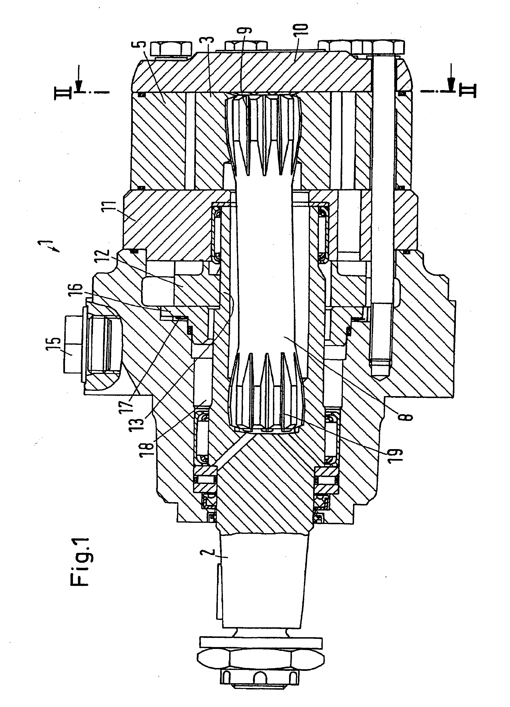
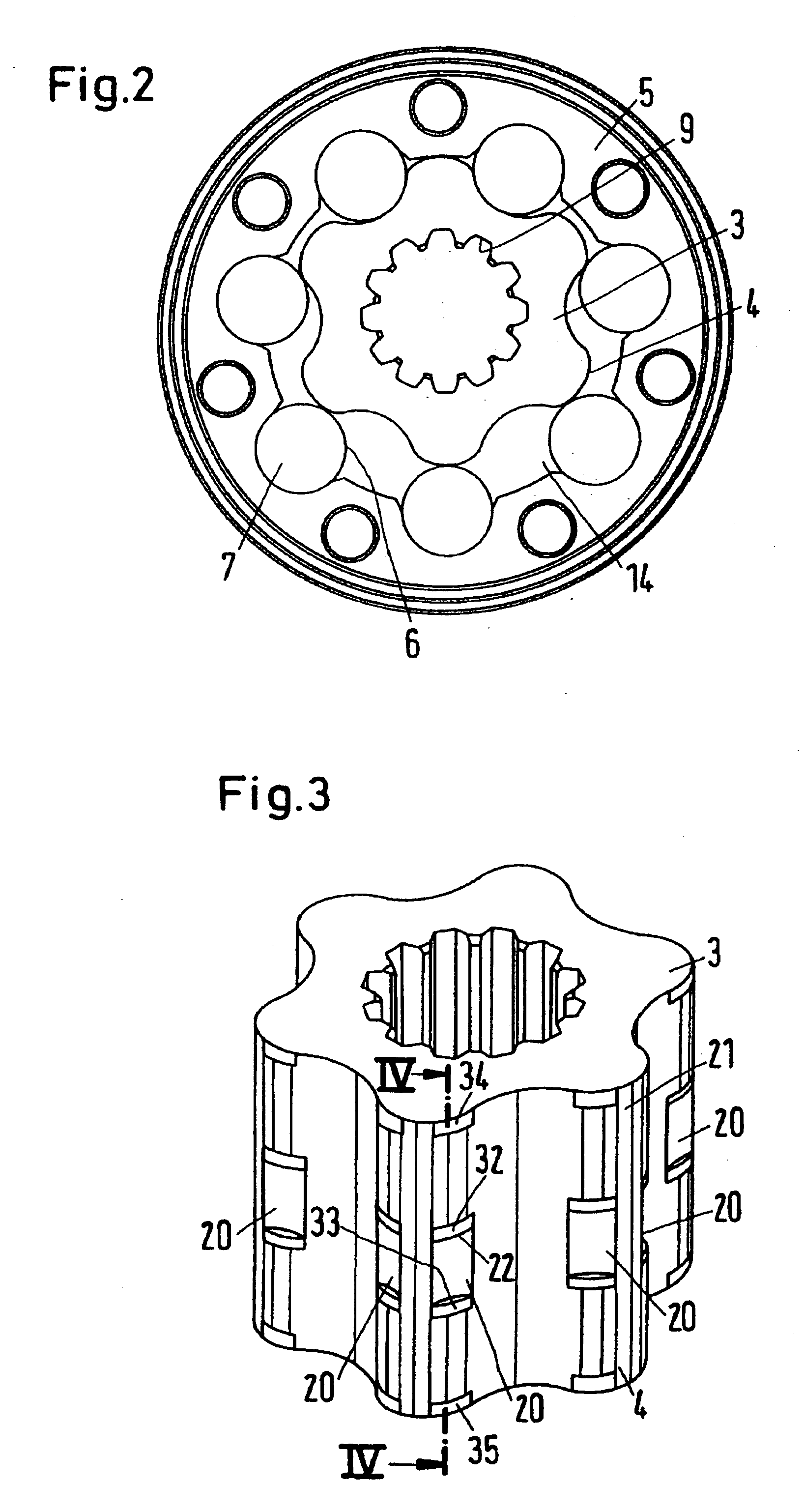
[0022] A machine shown in FIG. 1 has the form of a motor 1, which has an output shaft 2. The output shaft 2 is driven by a gear wheel 3, which has an outer toothing 4 and rotates and orbits in a toothed ring 5, which has an inner toothing 6 in the form of rolls 7. The output shaft 2 is connected with the gear wheel 3 via a cardan shaft 8, which is inserted in an accordingly suitable toothing 9 on the inside of the gear wheel 3.

[0023] On the side turning away from the cardan shaft 8, the toothed set consisting of gear wheel 3 and toothed ring 5 is covered by a cover plate 10. On the opposite side the toothed set is covered by a channel plate 11, which interacts with a valve plate 12. The valve plate 12 engages an extension 13 of the output shaft 2, so that the valve plate 12 rotates synchronously with and in a predetermined angle relation to the gear wheel 3.

[0024] The channel plate 11 and the valve plate 12 form a valve arrangement, which controls, by means of a connection arrange...


PUM


Abstract

The invention concerns a hydraulic machine with a toothed set comprising a toothed ring with an inner toothing, whose circumferential surface extends in parallel with its axis, and a gear wheel (3) with an outer toothing, whose circumferential surface (24) extends in parallel with its axis, at least one tooth flank having an edge as an axial end of a section, which is located between the circumferential surface and a surface directed radially inwards. It is endeavoured to reduce the wear. For this purpose it is ensured that in the radial direction an edge (22, 23) ends so as to be offset inwards in relation to the circumferential surface (24).

Description

CROSS-REFERENCE TO RELATED APPLICATIONS [0001] Applicant hereby claims foreign priority benefits under U.S.C. § 119 from German Patent Application No. 10 2004 046 934.2 filed on Sep. 28, 2004, the contents of which are incorporated by reference herein. FIELD OF THE INVENTION [0002] The invention concerns a hydraulic machine with a toothed set comprising a toothed ring with an inner toothing and a gear wheel with an outer toothing. BACKGROUND OF THE INVENTION [0003] In a hydraulic machine with a toothed set comprising a toothed ring with an inner toothing, whose circumferential surface extends in parallel with its axis, and a gear wheel with an outer toothing, whose circumferential surface extends in parallel with its axis, at least one tooth flank having an edge as an axial end of a section, which is located between the circumferential surface and a surface directed radially inwards. Such a machine is, for example, known from EP 0 959 248 A2. This machine has clearances or recesses,...

Claims


Application Information

Patent Timeline
Patent Type & Authority Applications(United States)
IPC IPC(8): F16N13/20F01C1/02F04C2/00F01C1/063F04C18/00
CPCF04C2/103F04C2/084
Inventor ANDERSEN, RENEHANSEN, KIM RENEJOHANSEN, CLAUS
Owner SAUER DANFOSS NORDBERG
Why Eureka
Try Eureka