Pattern decision method and system, mask manufacturing method, image-forming performance adjusting method, exposure method and apparatus, program, and information recording medium

a mask manufacturing and decision-making technology, applied in the field of patent decision-making methods and systems, can solve the problems of not being in the optimal adjustment position, not being able to use a common reticle among the plurality of exposure apparatuses, and not being able to correct only seidel's five aberrations (low order aberrations) in recent exposure apparatuses. to achieve the effect of manufacturing (fabricating) a mask commonly used

Inactive Publication Date: 2006-03-30
NIKON CORP
View PDF19 Cites 45 Cited by
  • Summary
  • Abstract
  • Description
  • Claims
  • Application Information

AI Technical Summary

Benefits of technology

[0013] The present invention was made under such circumstances, and has as its first object to provide a pattern decision method and

Problems solved by technology

In addition, because circuit patterns are becoming finer with higher integration in recent semiconductor devices or the like, correcting only Seidel's five aberrations (low order aberration) is no longer sufficient enough in recent exposure apparatus.
Accordingly, the adjusted position of each optical element by the image-forming performance adjustment mechanism that is optimal under a certain exposure condition may not be the optimal adjusted position under other exposure conditions.
That is, it may be difficult to use a common reticle among the plurality of exposure apparatus.
This is because the aberration state of the projection optical system of the exposure apparatus differs depending on the exposure apparatus (apparatus number), and the difference (discrepancy) in aberration among the exposure a

Method used


Image

  • Pattern decision method and system, mask manufacturing method, image-forming performance adjusting method, exposure method and apparatus, program, and information recording medium
  • Pattern decision method and system, mask manufacturing method, image-forming performance adjusting method, exposure method and apparatus, program, and information recording medium
  • Pattern decision method and system, mask manufacturing method, image-forming performance adjusting method, exposure method and apparatus, program, and information recording medium

Examples


Embodiment Construction

[0127] An embodiment of the present invention is described below, referring to FIGS. 1 to 18.

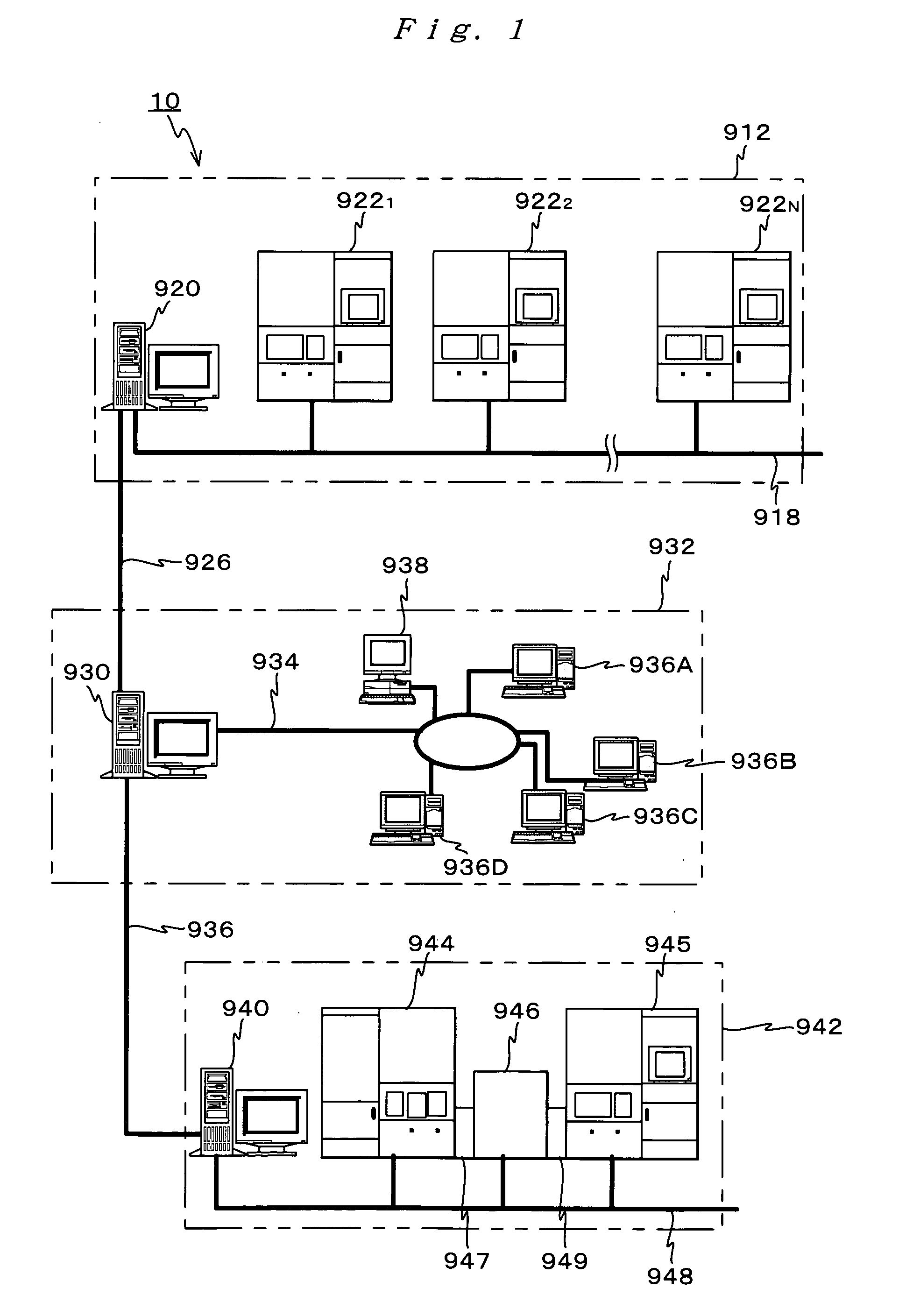
[0128]FIG. 1 shows an entire configuration of a device manufacturing system 10, which serves as a pattern decision system related to the embodiment, with a part of the configuration omitted.

[0129] Device manufacturing system 10 shown in FIG. 1 is a corporate LAN system built within a semiconductor factory of a device manufacturer (hereinafter referred to as ‘manufacturer A’ as appropriate) that is a user of device manufacturing units such as an exposure apparatus. Computer system 10 incorporates: a lithography system 912, which includes a first computer 920 and is arranged in a clean room; a reticle design system 932, which includes a second computer 930 that connects to the first computer 920 constituting lithography system 912 via a local area network (LAN) 926 serving as a communication channel; and a reticle manufacturing system 942, which includes a computer 940 used for production co...


PUM


Abstract

Based on adjustment information on the adjustment unit under predetermined exposure conditions and information on the corresponding image-forming performance of the projection optical system, pattern correction information, information on a permissible range of the image-forming performance, and the like, a calculation step (steps 114 to 118) and a setting step (steps 120, 124, and 126) are repeatedly performed in the case an image-forming performance in at least one exposure apparatus is outside the permissible range under the target exposure conditions until the image-forming performance in all the exposure apparatus is within the permissible range. In the calculation step, an appropriate adjustment amount under target exposure conditions whose pattern is corrected is calculated for each exposure apparatus, and in the setting step, the correction information is set according to a predetermined criterion based on the image forming performance outside the permissible range, and when the image-forming performance in all the exposure apparatus is within the permissible range, the correction information that has been set is decided as the pattern correction information (step 138).

Description

CROSS-REFERENCE TO RELATED APPLICATIONS [0001] This is a continuation of International Application PCT / JP2004 / 005481, with an international filing date of Apr. 16, 2004, the entire content of which being hereby incorporated herein by reference, which was not published in English. BACKGOUND OF THE INVENTION [0002] 1. Field of the Invention [0003] The present invention relates to pattern decision methods and systems, mask manufacturing methods, image-forming performance adjusting methods, exposure methods and apparatus, programs, and information recording mediums, and more particularly to a pattern decision method and a pattern decision system where information of a pattern that is to be formed on a mask is decided, a mask manufacturing method that uses the pattern decision method, an image-forming performance adjusting method of a projection optical system which projects the pattern formed on the mask onto an object, an exposure method that uses the image-forming performance adjustin...

Claims


Application Information

Patent Timeline
IPC IPC(8): G03C5/00G06F17/50G03F1/00G03F7/20G03F7/207
CPCG03F7/70258G03F7/70641G03F7/70533
Inventor HIRUKAWA, SHIGERU
Owner NIKON CORP
Why Eureka
Try Eureka