Endodontic instrument with depth markers

Inactive Publication Date: 2006-03-30
ORMCO CORP
View PDF41 Cites 38 Cited by
  • Summary
  • Abstract
  • Description
  • Claims
  • Application Information

AI Technical Summary

Benefits of technology

[0015] The plurality of markers of the invention may be used in conjunction with a selected datum to determine the depth of the instrument relative to the apex of the root canal. When the tip of the instrument nears the apex of the root canal, a practitioner will often take additional radiographs of the tooth while the endodontic instrument is disposed within the root canal. In the invention, as described herein, each marker on the instrument is clearly perceivable i

Problems solved by technology

A problem that may be encountered during root canal therapy is apical perforation, i.e., excessive perforation of the apex of the root canal.
Apical perforations typically result from pushing the tip of the endodontic instrument well beyond the apex of the canal, which not only exposes the periapical tissue to the infected debris, but also results in an enlarged and poorly shaped apex.
The exposure to the infected debris may result in sensitivity and lengthen the healing process, while the enlarged and poorly shaped apex may result in a bad seal, leading to apical leakage and ultimately the need for retreatment or tooth extraction.
Another problem relates to not introducing the file deep enough into the canal and failing to remove infected material from the vicinity of the apex, thereby leaving infected tissue within the root canal.
Electronic apex locators, however, are costly and unreliable under some circumstances.
A common problem with using moveable rubber stops to locate the apex is that after the radiograph is taken the rubber stop may be inadvertently moved by the patient while the instrument is still in the mouth, or by the practitioner while in the process of removing the instrument from the mouth, thereby rendering a false measurement.
Another issue with using rubber stops is that they are genera

Method used


Image

  • Endodontic instrument with depth markers
  • Endodontic instrument with depth markers
  • Endodontic instrument with depth markers

Examples


Embodiment Construction

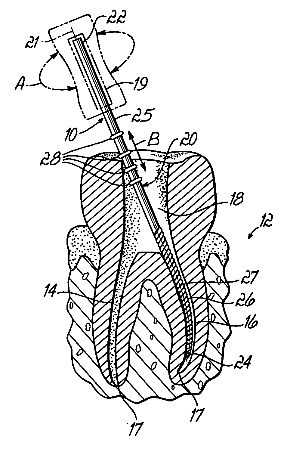
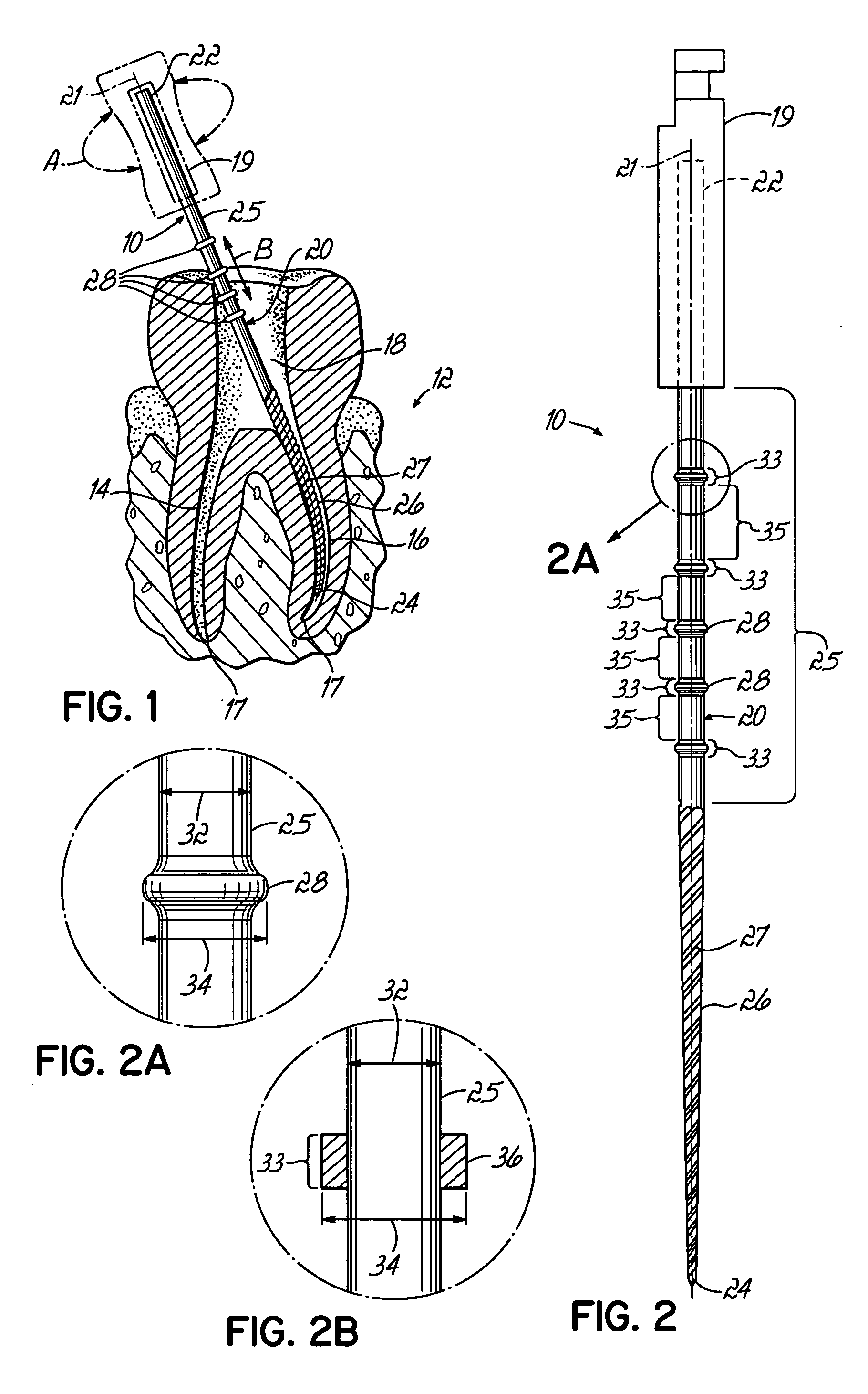
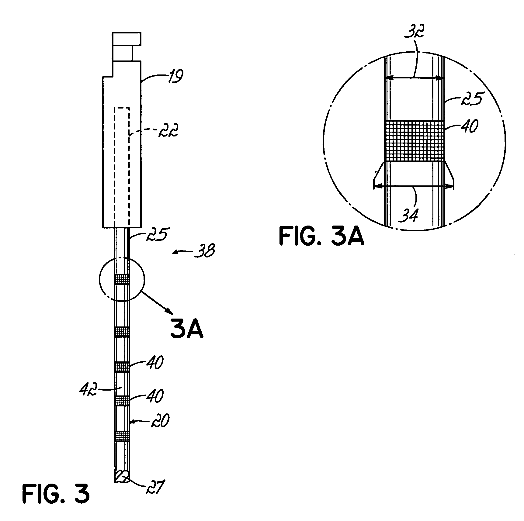
[0028] Referring first to FIG. 1, an endodontic instrument 10 constructed in accordance with an exemplary embodiment of the invention is shown being used during a root canal procedure on a tooth 12. Tooth 12 includes root canals 14 and 16 which terminate at the canal apex 17, and an upper interior cavity or pulp chamber 18 which has been initially opened using another instrument, such as a bur or drill (not shown). Instrument 10 includes an elongated shaft20 defining a longitudinal axis 21, a proximal end 22 and a distal end or tip 24, and a portion 26 adjacent tip 24 capable of being inserted into root canals 14 and 16 of tooth 12. Portion 26 may include a working length 27 having a cutting edge adapted to extirpate tissue and dentin from root canals 14 and 16, although the invention is not so limited. A shank 19 is situated at the proximal end 22 of elongated shaft 20 and adapted for interfacing or gripping instrument 10 with a chuck or collet of a motorized rotary dental handpiec...


PUM


Abstract

An endodontic instrument includes an elongated shaft having a tip and a portion capable of being inserted into the root canal of a tooth. The shaft further includes a plurality of depth markers which are perceivable in a radiograph for indicating the depth of the tip within the root canal. The markers may comprise bumps having a diameter greater than the diameter of the elongated shaft by an amount sufficient to distinguish the markers from the shaft on the radiograph. Alternately, or additionally, the markers may have a radiopacity different from the radiopacity of the shaft by an amount sufficient to distinguish the markers from the shaft on the radiograph. The shaft may be selectively coated with paints, dyes, and/or inks having radiopaque properties. The markers may take the form of circumferential rings or other indicia such as numerals, letters and/or geometrical shapes.

Description

FIELD OF THE INVENTION [0001] The invention relates generally to dental instruments and, more particularly, relates to endodontic instruments for extirpating pulp tissue and dentin from a root canal before obturating the root canal. BACKGROUND OF THE INVENTION [0002] Successful root canal therapy effectively alleviates the pain and trauma originating from the decayed, damaged or dead circulatory and neural pulp tissue so that the tooth need not be extracted. After the pulp chamber, and subsequently the coronal root canal orifice(s), have been accessed during a root canal procedure, pulp tissue is extirpated from the root canal(s) of the tooth. Some surrounding dentin is also removed in the shaping of the root canal(s). After the root canal(s) have been sufficiently shaped and cleaned, sealant and obturation materials are used to fill and seal the root canal(s). To conclude the procedure, the access cavity in the coronal portion of the tooth is sealed using a restorative procedure to...

Claims


Application Information

Patent Timeline
IPC IPC(8): A61C5/02
CPCA61C5/023A61C5/42
Inventor DESROSIERS, JOHN JOSEPHALOISE, CARLOS A.GARMAN, GARY T.GLICKER, BRIAN K.
Owner ORMCO CORP
Why Eureka
Try Eureka