Supersonic material flame spray method and apparatus

a supersonic material and flame spraying technology, applied in the direction of spray nozzles, plasma techniques, coatings, etc., can solve the problems of reducing the deposition efficiency of sprayed materials, compromising coating quality, and applying limitations to spraying materials, so as to reduce the problem of clogging

Inactive Publication Date: 2011-09-22
BARANOVSKI VIATCHESLAV E +1
View PDF12 Cites 18 Cited by
  • Summary
  • Abstract
  • Description
  • Claims
  • Application Information

AI Technical Summary

Benefits of technology

[0008]The present invention is related to a method of forming a coating by depositing a material onto a substrate with high-velocity thermal spray apparatus, wherein the apparatus comprises a mixing unit, a combustion chamber, and a non-clogging supersonic accelerating nozzle. The method comprises the steps of mixing of an oxidizer gas and a gaseous fuel in the mixing unit, igniting and combusting the oxidizer and gaseous fuel mixture in the combustion chamber, feeding products of combustion to the accelerating nozzle, introducing selected spraying material into accelerating nozzle to form a supersonic stream of hot combustion product gases with entrained particles of spray material, and spraying at high velocity onto a surface positioned in the path of the stream at the discharge end of the nozzle. The method further includes a step of forming a non...

Problems solved by technology

In spite of the technological advantages of higher particle velocities generated by supersonic convergent-divergent nozzles, there are some disadvantages caused by gaseous flow temperature drop in the divergent portion of the nozzle due to gas expansion.
So, lowered heating capacity of a supersonic gas flow further reduces particle temperature that, in turn, leads to lower deposition efficiency (DE) of sprayed material, compromises coating quality, and applies limitations for spraying materials with high melting points.
This cooling effect of expanded gas flow is even more detrimental for HVAF torches, since maximal temperature of combustion of air-fuel mixture in a combustion chamber is only about 1900° C., and exit gas temperature is about 1200° C. for typical stagnation pressure 6-7 bar, e.g. Mach numbers around 2.
So, the use of convergent-divergent nozzles with HVAF torches significantly compromises coating qu...

Method used


Image

  • Supersonic material flame spray method and apparatus
  • Supersonic material flame spray method and apparatus
  • Supersonic material flame spray method and apparatus

Examples


Embodiment Construction

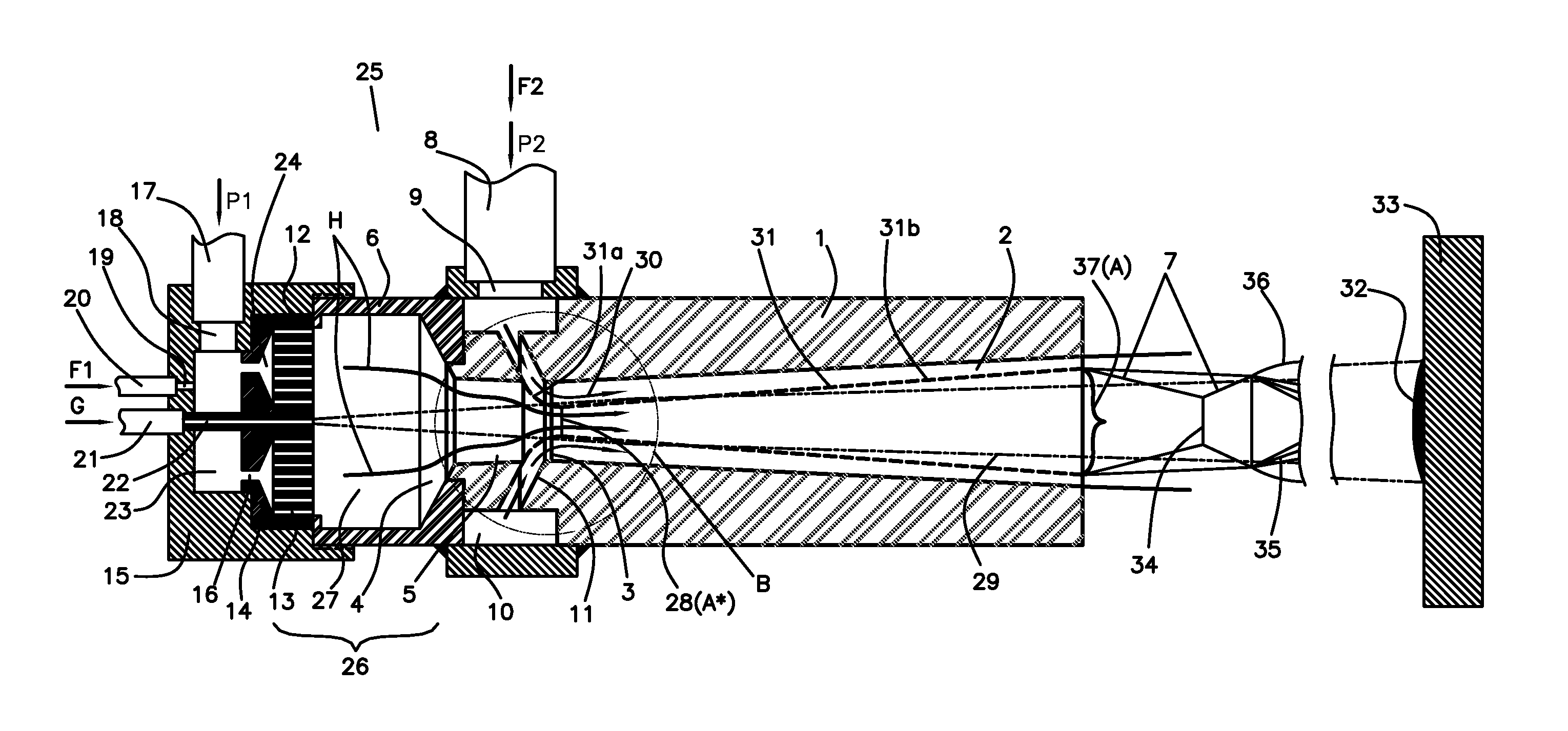
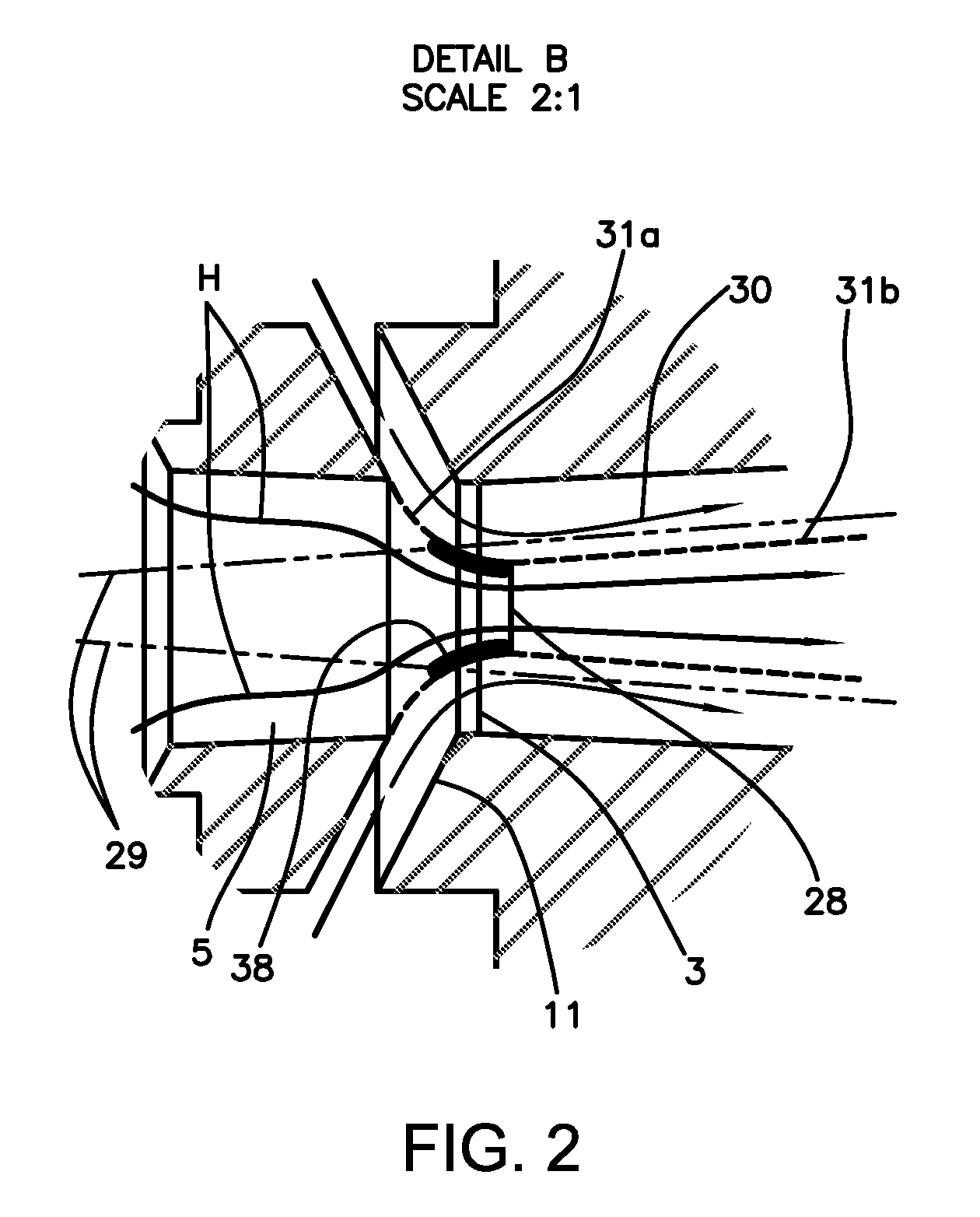
[0013]Referring to the drawing, a better understanding of the principles of this invention may be gauged by inspection of FIG. 1. In FIG. 1 an improved internal burner type supersonic velocity flame jet apparatus indicated generally at 25 takes the form of an internal burner 26 comprised of cylindrical section 6, which is closed off at its upstream end by a permeable burner block 12 and closed off at its downstream end by an exit accelerating nozzle piece 1, thus forming a combustion chamber 27 internally of burner 26. The accelerating nozzle piece 1 is provided with an axial nozzle bore, comprising an inlet bore 5 followed by an outlet diverging bore 2 that opens downstream. The radial dimension of an inlet bore 5 should be big enough in order to prevent heated powder stream 29 from touching the walls of the inlet bore 5. The inlet bore 5, which can be converging as shown in FIG. 1, diverging (not shown), or straight (not shown), or be of variable geometry (not shown), of the accel...


PUM

PropertyMeasurementUnit
Flow rateaaaaaaaaaa
Accelerationaaaaaaaaaa
Reactivityaaaaaaaaaa

Abstract

A method of forming a coating deposits a material onto a substrate with high velocity thermal spray apparatus. The method comprises the steps of mixing of an oxidizer gas and a gaseous fuel in the mixing unit, igniting and combusting the oxidizer and gaseous fuel mixture in the combustion chamber, feeding products of combustion to the accelerating nozzle, introducing selected spraying material into accelerating nozzle to form a supersonic stream of hot combustion product gases with entrained particles of spray material, and spraying at high velocity onto a surface positioned in the path of the stream at the discharge end of the nozzle; and forming a non-clogging convergent-divergent gas dynamic virtual nozzle (GDVN) in the accelerating nozzle by annularly introducing a coaxial gas flow, through a narrow continuous slot of circumferential ring geometry in the vicinity of the entrance to the diverging outlet bore of the accelerating nozzle.

Description

BACKGROUND OF THE INVENTION[0001]This invention relates in general to flame spray apparatus and to methods of deposition of coatings and bulk materials with thermal spray techniques. More specifically, the invention relates to high-velocity oxidizer-fuel spraying apparatus and methods.[0002]Thermal spraying is widely used to apply metals and ceramics in a form of coating or bulk materials on different types of substrates. A majority of thermal spray methods utilize energy of hot gaseous jets to heat and accelerate particles of spraying material. When impinging the substrate, the particles form a coating.[0003]High-Velocity Oxygen-Fuel (HVOF) spraying apparatus and techniques, which use oxygen as an oxidizer gas, or High-Velocity Air-Fuel (HVAF) spraying apparatus and techniques, which use air as an oxidizer gas, generate a jet of hot gases due to combustion of a fuel and oxidizer in an internal burner at elevated pressure, usually several bars. The fuel can be gaseous (e.g., propane...

Claims


Application Information

Patent Timeline
IPC IPC(8): B05D1/08B05B1/24
CPCB05B7/0815C23C4/124B05B7/205B05B7/0838C23C4/129
Inventor BARANOVSKI, VIATCHESLAV E.BARANOVSKI, ANDREW V.
Owner BARANOVSKI VIATCHESLAV E
Why Eureka
Try Eureka